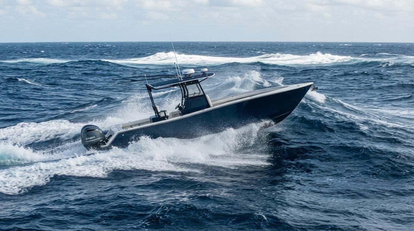
How CHIRP Cone Angle Determines Pelagic Sonar Coverage
A transducer’s cone angle determines the circular acoustic footprint across the water column and seabed according to the formula: Footprint Diameter = 2 × Depth × tan(Cone Angle / 2). Across pelagic CHIRP frequencies from 50kHz to 250kHz, beam angles scale inversely with frequency, spanning wide 25° to 50° spreads in Low CHIRP down to narrow 6° to 20° beams in High CHIRP. At a working depth of 300 feet, a 25° beam sweeps a 133-foot-wide circle, while a focused 9° beam covers just 47 feet. Selecting the wrong angle either leaves target pelagics undetected outside a pinhole beam or masks them inside acoustic clutter under a broad beam.
CHIRP stands for Compressed High-Intensity Radiated Pulse, a sonar transmission method that sweeps through a continuous spectrum of sound frequencies within a single burst rather than pinging at one fixed frequency.
This inverse relationship between frequency and coverage comes directly from diffraction physics. According to Robert J. Urick’s reference text, Principles of Underwater Sound, an acoustic transducer’s beam divergence angle (\(\theta\)) is governed by the ratio of acoustic wavelength (\(\lambda\)) to active ceramic element diameter (\(D\)), approximated by \(\sin(\theta/2) \approx 1.2 \times (\lambda / D)\). Because wavelength equals sound velocity divided by frequency (\(c / f\)), lowering the frequency from 200kHz to 50kHz quadruples acoustic wavelength. Without scaling the physical ceramic crystal to unwieldy dimensions, the sound wave diffracts outward more aggressively, forcing the acoustic beam to broaden dramatically at lower frequencies.
Airmar Technology Corporation’s engineering specifications show this physical reality across commercial hardware. The popular Airmar B175L transducer operates across 40kHz to 60kHz with a wide beamwidth between 32° and 21°. Conversely, the Airmar B175H operates across 130kHz to 210kHz, yielding a tight beamwidth between 15° and 9°.
When dropping vertical jigs at structure like the Marathon Humps Tuna: Jig Depth (Calculation Sheet), these geometry differences dictate your visual display. At 600 feet, a 32° cone projects an acoustic circle 344 feet wide across the bottom, whereas a 9° beam covers just 94 feet.
Wide-angle coverage carries severe operational trade-offs offshore. A wide cone integrates echoes across a larger volume of water, which introduces target masking from strong density boundaries. Thermoclines—sharp temperature gradients separating warm surface layers from cold depths—reflect and refract sound waves. In wide-cone Low CHIRP arrays, thermocline reverberation blankets the center of your display in white noise, hiding return signatures from target gamefish holding right on the temperature break.
Surface turbulence and aeration create a secondary masking zone. In heavy sea states, hull-induced microbubbles sweep under the face of a hull-mounted or thru-hull transducer. Because low-frequency acoustic energy disperses outward so broadly, it illuminates this entire near-surface layer of turbulence, blowing out the top 30 to 80 feet of the water column.
Vessel dynamics further complicate wide-beam tracking. When a boat rolls 10° in ocean swells, a 25° transducer sweeps its coverage cone across a 45° dynamic arc. At depths where anglers deploy gear using a Slow Pitch Jig Weight Chart: 100 to 800 Feet (Chart), this roll shifts the monitored patch of bottom hundreds of feet laterally with every passing wave, resulting in jagged bottom profiles and false drop-offs. Narrower beams minimize surface reverberation and thermocline interference, but demand precise boat positioning directly above pelagic schools.
To balance coverage volume against display clarity during offshore trips, technicians apply a structured calibration procedure over their initial runs.
5-Day Sonar Beam Calibration Plan
Gate: Stop tuning if High CHIRP fails to distinguish two terminal weights separated by 18 inches at 150 feet; element alignment or ceramic sensitivity requires servicing before proceeding.
Understanding these beamwidth dynamics allows you to dial in ping speed, gain filters, and pulse lengths against the water column depth you plan to target next.
Mathematical Formula for Calculating Sonar Beam Footprint Diameter
The acoustic footprint diameter of an active sonar beam is calculated using the planar trigonometry formula: Beam Diameter = 2 × Depth × tan(Cone Angle / 2).
Transducer cone angle is the angular width of the transmitted acoustic energy cone, measured at the points where acoustic intensity drops by 50% relative to the center of the main acoustic axis.
This calculation assumes a flat seabed, where the acoustic wave front forms a right-angled triangle between the transducer face, the center point on the bottom, and the edge of the transmitted acoustic axis.
       Transducer Face
             |
            / \
           / | \   Cone Angle (θ)
          /  |  \
         /   |   \
        /    |D   \
       /     |     \
      /______|______\
     <-- r --><-- r -->
      Total Diameter
If you fish an Airmar Technology Corporation B175H single-channel CHIRP transducer running a fixed 9° high-frequency beam at 600 feet, calculate the radius first: \(600 \times \tan(4.5^\circ) = 600 \times 0.0787 = 47.22\text{ feet}\).
Multiplying that radius by two yields a beam footprint diameter of 94.44 feet across the bottom.
When you track pelagics across structured drop-offs, precision footprint calculations tell you exactly how much bottom your cone covers relative to vertical jig presentations, like those charted in the Marathon Humps Tuna: Jig Depth (Calculation Sheet).
Running tangent calculations while running offshore at 25 knots is impractical, so helmsmen rely on two geometric multipliers derived from standard CHIRP beam widths.
For narrow 6° beams—common on low-frequency CHIRP elements such as the Airmar B275LHW low band—apply the 1:10 rule.
Because \(2 \times \tan(3^\circ) \approx 0.1048\), your beam diameter closely equals 10% of your current depth.
At 1,000 feet of depth, a 6° beam illuminates a tight 105-foot circle on the bottom.
For wide 28° beams—standard on high-wide pelagic searching transducers—apply the 1:2 rule.
Because \(2 \times \tan(14^\circ) \approx 0.4986\), your beam diameter closely matches 50% of your display depth.
At 200 feet below your hull, a 28° beam covers a 100-foot diameter circle, providing instant spatial awareness when tracking bait schools alongside your trolling spread, much like balancing wire weights against depth in Downrigger Blowback: True Depth at 80-180ft (With Chart).
    BEAM RATIO CHEAT SHEET
    ----------------------
    6° Beam  = 1:10 Ratio
    (Depth × 0.10 = Footprint)

    28° Beam = 1:2 Ratio
    (Depth × 0.50 = Footprint)
Sonar screens display targets that exist outside these calculated diameters because transducer beams do not terminate at a hard geometric edge.
Robert J. Urick’s classic reference, Principles of Underwater Sound, notes that the marine electronics industry defines beam angle at the -3dB half-power boundary.
At this -3dB threshold, acoustic transmission power drops to 50% of the peak axial output, and sound pressure drops to 70.7%.
Significant acoustic energy spills beyond this nominal boundary into the peripheral main lobe and adjacent acoustic side lobes.
When an apex pelagic swims through this -3dB fringe zone, the fish returns an echo to the transducer, but the sonar unit calculates return distance based solely on travel time along the acoustic axis.
Because an off-axis fish sits along an angled slant-range rather than directly below the boat, the receiver places that fish deeper on your display than its actual physical depth.
This slant-range distortion flattens and extends the acoustic target, creating exaggerated, asymmetrical fish arches that betray targets drifting just outside your nominal cone.
Try This Today: Calculate your primary transducer’s exact coverage circle for your next trip’s target depth in under five minutes. Look up your transducer model’s nominal cone angle in its manual, enter the angle into your smartphone calculator as tan(angle / 2), and multiply that figure by twice your expected fishing depth to log your working beam diameter.
Knowing your footprint diameter establishes how much water you inspect, but dynamic boat motion and target speed alter how many acoustic pings hit a moving fish before it exits that cone.
Acoustic Attenuation and Target Separation from 50kHz to 250kHz
Selecting the correct CHIRP sonar transmission frequency between 40kHz and 250kHz governs the physical trade-off between acoustic penetration depth and axial target separation.
Acoustic attenuation is the progressive rate at which sound pressure waves lose energy as they travel through seawater due to spherical spreading, viscous thermal absorption, and chemical relaxation processes.
According to absorption models established by the Acoustical Society of America, sound absorption in standard 10°C seawater increases sharply with frequency: a 50kHz pulse loses roughly 13 dB/km, while a 200kHz pulse dissipates approximately 54 dB/km.
Low CHIRP (40kHz–60kHz): Deep-Water Penetration
Low-frequency pulses bypass the rapid viscous damping that absorbs higher acoustic energy, making 40kHz–60kHz transducers the standard for tracking structure past 1,000 feet. At depths exceeding 1,500 feet along canyon walls, high frequencies drop below the thermal noise floor of the receiver. Low CHIRP maintains the acoustic power necessary to trace deep scattering layers, identify oceanic thermoclines, and map bottom contours when setting up drifts with a Slow Pitch Jig Weight Chart: 100 to 800 Feet (Chart).
The trade-off is vertical target resolution. Because the sweep bandwidth (\(\Delta f\)) in low-band transducers typically spans only 20kHz, theoretical axial target separation is limited to approximately 37.5 mm. You will clearly mark deep structural ledges and macro-biomass layers, but you cannot isolate individual predatory fish positioned inches from the bottom or packed tightly inside a school.
Medium CHIRP (80kHz–130kHz): The Pelagic Sweet Spot
Medium CHIRP bridges deep-water reach and target clarity, operating as the primary search frequency for pelagic gamefish between 200 and 600 feet. With attenuation rates averaging 22 dB/km across this band, acoustic energy easily reaches the mid-water hunting zones of tuna and billfish without requiring excessive amplifier gain.
Transducers in this band provide 50kHz of swept bandwidth, improving axial resolution to approximately 15 mm. When targeting feeding schools over offshore seamounts as detailed in the Marathon Humps Tuna: Jig Depth (Calculation Sheet), Medium CHIRP separates individual tuna arcs from dense squid schools where Low CHIRP would show a solid, indistinct acoustic blob.
High CHIRP (130kHz–250kHz): Precision Separation
High CHIRP operates where acoustic absorption is severe, limiting its practical pelagic depth to roughly 200 to 400 feet depending on transducer output wattage. The physical payoff lies in target resolution: a 100kHz sweep bandwidth (such as 150kHz to 250kHz) yields an axial resolution of 7.5 mm based on the pulse compression formula \(R = c / (2B)\), where \(c\) represents acoustic velocity (1,500 m/s) and \(B\) represents bandwidth.
This resolution enables you to distinguish individual gamefish shadowing or punching through dense bait pods. Standard narrow-beam High CHIRP ceramics project tight cone angles between 6° and 10°, concentrating energy into an acoustic pinpoint that delivers crisp returns of marlin bills and individual trailing fish under the boat.
High-Wide (HW) Variants: Beam Geometry Without Resolution Loss
Standard high-frequency transducers suffer from narrow seabed coverage: a 6° beam covers an inspection circle only 10.5 feet across at a depth of 100 feet. To solve this, transducer manufacturer Airmar Technology Corporation developed High-Wide (HW) ceramic elements, such as those in the B175HW, which maintain a constant 25° beam width across the entire 150kHz to 250kHz sweep.
The fixed 25° cone projects an acoustic footprint roughly 44 feet across at a 100-foot depth, quadrupling your surveyed water volume. Because the transducer still sweeps a wide 100kHz frequency range, it retains its 7.5 mm axial target separation, letting you monitor surface-to-mid-depth pelagics across an expanded scanning zone.
CHIRP Band
Typical Frequency Sweep
Attenuation Rate (at 10°C)
Axial Target Separation
Effective Pelagic Search Depth
Primary Target Application
Low
40kHz – 60kHz
~13 dB/km
~37.5 mm
800 to 3,000+ ft
Canyon walls, deep drop-offs, deep scattering layers
Pinpoint gamefish tracking, hard bottom separation
High-Wide (HW)
150kHz – 250kHz
~54 dB/km
~7.5 mm
Surface to 300 ft
Upper water column coverage, billfish tracking around bait
Calculating your transducer’s true footprint at targeted depths requires converting these angular ratings into exact water-column coverage diameters.
Pelagic Depth Coverage Chart for Standard CHIRP Frequencies
A CHIRP transducer cone angle dictates your effective acoustic search volume, scaling the seafloor footprint from a narrow 10.5-foot diameter circle at 100 feet with a 6° beam to a 443.4-foot swath at 1,000 feet with a 25° wide-beam element. According to engineering documentation published by Airmar Technology Corporation, selecting the wrong element profile causes anglers either to miss pelagic schools entirely outside an undersized cone or to lose critical target separation inside an excessively wide beam.
Transducer beam angle is the angular diameter of the transmitted acoustic cone measured at the half-power points where acoustic intensity drops by three decibels relative to the central acoustic axis.
Because sound energy diverges geometrically as it propagates, linear coverage diameter expands predictably with depth according to the formula:
The following matrix contrasts beam diameters and seafloor circular footprints across primary recreational pelagic frequencies and beam angles.
Beam Angle
Standard Transducer Element
50 ft Depth (Dia. / Area)
100 ft Depth (Dia. / Area)
250 ft Depth (Dia. / Area)
500 ft Depth (Dia. / Area)
1,000 ft Depth (Dia. / Area)
6°
Custom Narrow / In-Hull High
5.2 ft / 21 sq ft
10.5 ft / 86 sq ft
26.2 ft / 539 sq ft
52.4 ft / 2,156 sq ft
104.8 ft / 8,626 sq ft
9°
Airmar B175H (210 kHz edge)
7.9 ft / 49 sq ft
15.7 ft / 194 sq ft
39.4 ft / 1,219 sq ft
78.7 ft / 4,865 sq ft
157.4 ft / 19,458 sq ft
16°
Airmar B175M (135 kHz edge)
14.1 ft / 156 sq ft
28.1 ft / 620 sq ft
70.3 ft / 3,882 sq ft
140.5 ft / 15,504 sq ft
281.1 ft / 62,060 sq ft
20°
Airmar B175L (60 kHz edge)
17.6 ft / 244 sq ft
35.3 ft / 978 sq ft
88.2 ft / 6,110 sq ft
176.3 ft / 24,412 sq ft
352.7 ft / 97,698 sq ft
25°
Airmar B175HW (Constant High-Wide)
22.2 ft / 387 sq ft
44.3 ft / 1,544 sq ft
110.8 ft / 9,642 sq ft
221.7 ft / 38,601 sq ft
443.4 ft / 154,405 sq ft
45°
Dual-Frequency Pelagic Low / Commercial
41.4 ft / 1,346 sq ft
82.8 ft / 5,385 sq ft
207.1 ft / 33,687 sq ft
414.2 ft / 134,748 sq ft
828.4 ft / 538,992 sq ft
The trade-off between target separation and coverage area determines your detection thresholds. A narrow 9° beam from an Airmar B175H concentrates acoustic energy into a tight axis, producing crisp returns and distinguishing individual blackfin tuna holding near bottom drop-offs like the Marathon Humps Tuna: Jig Depth (Calculation Sheet). Conversely, the B175HW maintains a constant 25° beam across its entire 150–250 kHz sweep, providing 7.9 times the detection area of a 9° transducer at an identical depth.
Volumetric Water-Column Mapping at Trolling Speeds
Static circular footprints do not reflect pelagic trolling dynamics. When running at open-water speeds between 7 and 9 knots, your transducer sweeps a continuous three-dimensional wedge through the water column. The cross-sectional scanning geometry resembles an inverted triangle, where total water volume sampled per hour depends on both vessel speed and beam dispersion.
At a trolling speed of 8 knots, a vessel covers 48,609 linear feet per hour over ground. Calculating swept volume through the top 250 feet of the water column exposes massive performance gaps between transducer classes:
Calculate the triangular cross-sectional area of the acoustic cone:
Multiply half the beam diameter at target depth by the depth itself (\(\text{Area} = 0.5 \times D \times \text{Depth}\)). For a 25° beam (B175HW) at 250 feet, this produces \(0.5 \times 110.8\text{ ft} \times 250\text{ ft} = 13,850\text{ sq ft}\). For a 9° beam (B175H), this yields \(0.5 \times 39.4\text{ ft} \times 250\text{ ft} = 4,925\text{ sq ft}\).
Compute vessel distance per hour at target trolling speed:
Convert velocity in knots to feet per hour by multiplying speed by 6,076.12 feet per nautical mile. An 8-knot trolling pass yields \(8 \times 6,076.12 = 48,609\text{ linear feet per hour}\).
Derive total cubic volume monitored:
Multiply the cross-sectional area by linear distance traveled. The 25° beam scans \(13,850\text{ sq ft} \times 48,609\text{ ft} = 673,234,650\text{ cubic feet per hour}\) (\(24.9\text{ million cubic yards}\)). The 9° beam covers \(4,925\text{ sq ft} \times 48,609\text{ ft} = 239,399,325\text{ cubic feet per hour}\).
Adjust for speed variances:
At 7 knots (42,533 feet per hour), the 25° beam samples \(589.1\text{ million cubic feet}\). At 9 knots (54,685 feet per hour), that volume expands to \(757.4\text{ million cubic feet}\), matching the rapid search grids used alongside the High-Speed Wahoo Sinker Chart (16oz to 96oz Depth Guide).
According to MacLennan and Simmonds in their reference text Fisheries Acoustics, target tracking reliability requires at least three consecutive acoustic pings to strike a fish as the beam passes overhead. At 8 knots, a fish suspended at 100 feet remains inside a 9° cone for only 1.16 seconds, requiring ping rates exceeding 3 Hertz to generate a verifiable arch. Inside a 25° cone, that same target stays illuminated for 3.28 seconds, yielding unmistakable arches even when running downriggers that suffer severe drag as mapped in our Downrigger Blowback: True Depth at 80-180ft (With Chart).
However, wide beams present acoustic dead zones when charting steep continental shelves or canyons. Acoustic energy striking shallow structure on the fringe of a 25° cone returns to the receiver before the deeper pulse strikes the centerline, masking targets holding near the bottom beneath an artificial bottom floor reading. Knowing how acoustic pulse lengths interact with element ringing reveals why high-chirp frequencies retain crisp target edges where low-chirp wide beams turn into unreadable clutter.
The Pelagic CHIRP Frequency and Depth Decision Matrix
Acoustic cross-talk is the interference pattern that occurs on a sonar display when two or more transducers emit sound pulses at identical or overlapping frequencies within the same body of water. Matching the target pelagic species to specific transducer beam angles and frequencies dictates whether you mark distinct fish arches or render an unreadable screen cluttered with surface noise and sidelobe returns.
Target Species Acoustic Profiling
Different pelagic species possess distinct physical characteristics that alter their acoustic target strength. According to acoustic surveys published by the Food and Agriculture Organization (FAO), a fish’s swim bladder accounts for approximately 90% of its backscattered acoustic energy.
Yellowfin Tuna (Thunnus albacares): Yellowfin lack large swim bladders relative to their body mass, resulting in weak acoustic target strength. When tracking tuna schools staged around current seams or subsurface structure, deploy High-Wide CHIRP (150–250 kHz with a fixed 25-degree cone). This setup resolves individual targets in the upper 300 feet (91 meters) of the water column. Pair this acoustic profile with the Marathon Humps Tuna: Jig Depth (Calculation Sheet) to place vertical jigs directly in the sonar-identified strike zone.
Blue Marlin (Makaira nigricans): Marlin roam the surface boundary layer down to 200 feet (61 meters). Their large mass and distinct swim bladder produce strong echo returns, but their high speed demands wide spatial coverage. A 25-degree high-frequency beam maintains coverage of a 133-foot-wide swath of water at a depth of 300 feet, keeping raised fish visible beneath your spread.
Swordfish (Xiphias gladius): Daytime swordfish concentrate near bottom structure along the continental shelf at depths between 1,200 and 1,800 feet (365 to 548 meters). At these depths, high frequencies attenuate completely. Detecting a swordfish or its bait layer requires Low CHIRP (42–65 kHz) transmitted through a narrow beam angle (under 12 degrees) to concentrate energy and avoid wide-beam bottom averaging. If you drop deep baits, match your drift rate to the Slow Pitch Jig Weight Chart: 100 to 800 Feet (Chart) or heavier lead configurations to maintain vertical alignment beneath the narrow cone.
Wahoo (Acanthocybium solandri): Wahoo lack a swim bladder entirely, making them exceptionally poor acoustic reflectors. To track wahoo running beneath fast-moving surface spreads, run Medium CHIRP (85–135 kHz) at a 16-to-21-degree beam angle. This configuration retains sufficient pulse energy to reflect off their dense skeletal structure while you coordinate trolling leads using the High-Speed Wahoo Sinker Chart (16oz to 96oz Depth Guide).
Operational Split-Screen Presets: Deep-Drop vs. Trolling
Switching between surface trolling and daytime deep-dropping demands distinct multi-frequency split-screen presets on your multi-function display.
[DEEP-DROP PRESET]
Window 1: Low CHIRP (42-65 kHz)
- Cone: 9° to 12° Narrow
- Target: 1,000-2,000 ft Seabed
        |
        v
Window 2: Medium CHIRP (85-135 kHz)
- Cone: 16° to 21° Moderate
- Target: 400-800 ft Deep Scatter

[TROLLING SPREAD PRESET]
Window 1: High-Wide CHIRP (150-250 kHz)
- Cone: 25° Constant Wide
- Target: 0-300 ft Pelagic Zone
        |
        v
Window 2: High CHIRP (130-210 kHz)
- Cone: 6° to 10° Focused
- Target: Exact Target Depth ID
For daytime deep-dropping, assign your low-frequency channel to full-screen or 70% primary split. Transducers like the Airmar Technology Corporation PM111LH or CM599LH pump 2 to 3 kilowatts of power across 42–65 kHz, which penetrates the thermocline and reaches depths past 1,500 feet. Set Window 2 to Medium CHIRP (85–135 kHz) zoomed into the deep scattering layer (typically 600 to 900 feet) where pelagic squid concentrate.
For high-speed trolling spreads, configure Window 1 to High-Wide CHIRP (150–250 kHz with a uniform 25-degree cone). This provides wide lateral tracking under the outriggers. Configure Window 2 to a discrete, non-swept single frequency (such as 200 kHz) or a narrow High CHIRP band (such as 175–210 kHz) to verify whether a mark on the wide beam sits directly under the keel or out on the margins.
Multi-Frequency Black Box Configuration
Modern dual-channel sounder modules, such as the Garmin GSD 26 or the Simrad S5100, process two independent acoustic channels simultaneously. Running these channels without physical frequency separation introduces acoustic cross-talk, visible as vertical spiking, repetitive diagonal dashed lines, or artificial bottom clutter.
To eliminate interference:
Ensure your high and low channels maintain a minimum 40 kHz frequency buffer between band limits. A channel sweeping 42–65 kHz will never conflict with a channel sweeping 130–210 kHz.
If running dual high-frequency sources (for example, pairing a 1 kW wide-beam hull transducer with a transom-mount 3D structure scanner), manually lock the CHIRP bands. Set one transceiver to sweep 135–175 kHz and lock the second to 190–225 kHz.
Disable auto-ping rates across asynchronous black boxes. When two standalone sounders ping independently, set their ping transmission rates to fixed intervals, or sync them via hardware transmit-trigger cables (such as Furuno’s KP synchronization protocol) to prevent simultaneous pulse emission.
Access your multi-function display’s sounder installation menu today, manually set your high and low CHIRP band limits to enforce a 40 kHz frequency buffer, and clear the screen clutter before your next pelagic run.
Sources & Further Reading
Calculating acoustic footprint and energy density across 50kHz to 250kHz CHIRP frequencies relies on physical hydroacoustic laws verified by marine electronics manufacturers and oceanographic survey institutions.
Transducer beamwidth is the angle measured across the central cone of sound where radiated acoustic power drops to half of its peak intensity, commonly referred to as the minus three-decibel point. When tracking pelagic species across the water column, acoustic geometry dictates that a wide 25-degree cone covers a floor diameter roughly equal to 44% of total water depth, while a narrow 6-degree beam covers only 10%. Marine hydroacoustics literature from institutions like the National Oceanic and Atmospheric Administration and technical engineers at Airmar Technology Corporation establish the empirical models behind these beam footprint calculations and pulse-compression dynamics.
MacLennan, D. N., & Simmonds, E. J. (2005). Fisheries Acoustics (2nd ed.). Blackwell Science. Explains target strength estimation and acoustic scattering across variable frequencies in marine environments.
Urick, R. J. (1983). Principles of Underwater Sound (3rd ed.). McGraw-Hill. Establishes the foundational active sonar equations and volumetric reverberation models used in sound propagation.
Airmar Technology Corporation. Airmar Transducer Technical Reference. Details ceramic element resonance, operational beam angles, and acoustic power dissipation across broadband CHIRP frequency bands.
National Oceanic and Atmospheric Administration (NOAA) Fisheries. (2018). Acoustic Survey Protocols for Marine Pelagic Species. Demonstrates spatial coverage modeling and multi-frequency sounder calibration for target tracking in open water.
Foote, K. G. (1987). Fish target strengths for use in echo integrator surveys. The Journal of the Acoustical Society of America. Correlates swim bladder cross-sectional area with frequency-dependent acoustic reflection.
Optimal Lens Tints for Core Water and Sky Conditions
Sight fishing lens tint selection requires balancing Visible Light Transmission (VLT) against environmental contrast: high-glare open blue water demands a 10% to 12% VLT gray base with a blue mirror, variable or shallow flats require a 12% to 15% VLT copper or amber base with a green mirror, and low-light overcast demands 25% to 35% VLT yellow or rose lenses. Matching base tint to bottom composition and mirror coating to surface glare optimizes depth penetration instantly. Selecting a lens based on sky brightness alone, however, produces severe target acquisition failures once that light enters the water column.
Visible Light Transmission (VLT) is the standardized percentage of ambient light within the visible spectrum—measuring 380 to 740 nanometers—that successfully penetrates an optical lens to strike the human retina.
When anglers select eyewear based solely on overhead lux rather than submerged optical characteristics, acute ocular fatigue develops within 90 minutes. In a study published by the Smithsonian Environmental Research Center, researchers documented how dissolved organic matter (CDOM) and suspended sediment shift spectral transmission toward longer wavelengths, absorbing short-wave blue light and scattering ambient photons. If you place a neutral-density gray lens over an estuary rich in tannins or suspended algae, you attenuate the exact yellow-red wavelengths needed to distinguish target species from structure. The human pupil dilates to compensate for the 10% VLT gray filter, yet the lens strips away the chromatic contrast required to resolve benthic edges, forcing the ciliary muscles to overwork while silhouettes blur into the background.
The underlying mechanical challenge is the optical conflict between polarized light filtering and target silhouette contrast at depth. According to Brewster’s Law, unpolarized sunlight striking water at approximately 53 degrees from the vertical undergoes maximum linear polarization through surface reflection. A linear polarizing film aligned at 90 degrees to this plane extinguishes this blinding horizontal sheen.
Beneath that surface film, however, light ceases to be linearly polarized; it undergoes isotropic Rayleigh and Mie scattering as it collides with water molecules and particulate matter. As depth increases past 2 meters, target detection relies entirely on luminance contrast—the luminance difference between the fish’s dorsal surface and the substrate. A dark gray lens eliminates too much scattered return light, reducing target luminance below the human eye’s minimum threshold for spatial edge detection. Amber, copper, and rose bases address this trade-off by blocking high-energy visible (HEV) blue light, which sharpens edges across sand, marl, and turtle grass without starving the optic nerve of usable detail.
Quick Quiz: Test Your Optical Calibration
1. An angler tracking cruising fish over a mixed turtle grass and sand flat under broken cloud cover switches from a 14% VLT copper lens to a 10% VLT neutral gray lens. Which diagnostic failure occurs first?
A. Excessive surface glare burns out retinal photoreceptors.
B. Loss of chromatic contrast causes grass edges and cruising fish to merge into a single dark plane.
C. The polarized film induces chromatic aberration across sand patches. Reveal answer
B. Gray lenses decrease light transmission evenly across all spectra, destroying the specific red-green chromatic separation required to spot silhouettes against mottled vegetation; for specific rigging and stalking setups over flats, review the tactics in Tarpon Fishing Islamorada.
2. Why does a deep-blue mirror coating provide a distinct visual advantage over open pelagic water, but fail over an inland tannic river?
A. Blue mirrors reflect yellow wavelengths while amplifying blue water backscatter.
B. Dielectric blue mirrors selectively reflect harsh blue light off deep, clear water; over brown water, they block the only penetrating warm wavelengths.
C. Blue mirrors reduce total VLT below 5%, which violates ANSI Z80.3 standards. Reveal answer
B. Dielectric blue mirrors reflect high-intensity blue light common in offshore Jerlov Type I waters, but in tannin-stained waters where only amber-red wavelengths penetrate, blue-mirrored gray lenses starve the eye of visible light.
3. You are sight fishing under a dense 500-foot cloud deck at 7:30 AM with water visibility down to 3 feet. Which optical configuration maintains silhouette detection?
A. 10% VLT gray base with silver mirror.
B. 14% VLT copper base with green mirror.
C. 30% VLT high-contrast yellow or light rose base with an anti-reflective interior coating. Reveal answer
C. Low-ambient environments require maximum photon transmission (25% to 35% VLT) combined with selective blue-light filtration to distinguish moving biological mass in low-lux conditions.
Understanding these spectral boundaries establishes the baseline for choosing your eyewear, but translating this physics into split-second target recognition on the water requires indexing each lens profile directly against your target depth and substrate profile.
Key Takeaways
Copper and amber bases deliver optimal contrast across 70% of variable freshwater and flats conditions.
Low-light yellow and high-transmission rose lenses excel under heavy overcast with 25% to 35% VLT.
Deep blue mirrors over gray bases cut intense offshore glare under unobstructed direct sunlight.
Green mirrors over amber bases sharpen structure outlines in stained, brackish, or tannic waters.
Physics of Polarized Light Transmission and Base Tints
Polarized fishing lenses control optical target acquisition by filtering horizontally reflected glare via an aligned polyvinyl alcohol iodine filter while tuning the spectral curve via the lens base substrate.
Visible Light Transmission is the percentage of electromagnetic radiation within the human photopic spectrum (380 to 750 nanometers) that penetrates an optical lens to reach the ocular retina.
According to optical safety thresholds codified in the American National Standards Institute ANSI Z80.3 benchmark, sport fishing sunglasses group into three functional VLT categories:
Low transmission (9% to 12% VLT): Engineered for cloudless offshore environments with illuminance exceeding 80,000 lux.
Medium transmission (13% to 18% VLT): General-purpose performance tuned for variable skies and mixed glare profiles.
High transmission (25% to 35%+ VLT): Low-lux applications designed for dawn, heavy cloud decks, and river canopies where ambient light drops below 10,000 lux.
A neutral gray base reduces overall photon influx uniformly across all wavelengths without skewing natural color profiles. Data published by the National Institute of Standards and Technology shows that flat-attenuation gray filters maintain an even spectral response across the visible spectrum. This makes a 10% VLT gray base effective for offshore trolling or open flats under a direct overhead sun where total brightness causes eye fatigue.
However, gray lenses degrade target separation in stained or brackish environments. When you sight-cast in water loaded with tannins, dissolved organic matter attenuates short-wave blue light while scattering green and red spectrums. A gray lens absorbs light uniformly, suppressing the faint reflective contrast between a dark fish flank and a muddy bottom.
Amber, bronze, and copper bases function as chromatic high-pass filters by selectively attenuating high-energy visible blue light between 400 and 490 nanometers. By truncating this blue haze—a primary driver of atmospheric and intra-water Rayleigh scattering—these warm bases increase edge definition between objects of differing refractive indices. Research in the Journal of the Optical Society of America confirms that selectively blocking high-frequency blue photons improves spatial acuity and chromatic contrast under overcast conditions.
In field scenarios like flats stalking for migratory species, copper bases highlight sub-surface substrate changes, transforming subtle shadows into distinct shapes. Anglers targeting cruisers along shallow oceanic edges, such as flats runs documented in Tarpon Fishing Islamorada, run copper or bronze bases to spot fish traversing mottled turtle grass and coral patches.
Specialty high-transmission bases like high-contrast yellow and vermillion operate between 28% and 35% VLT to maximize luminous throughput during dawn feeds and afternoon squalls. Yellow bases transmit up to 85% of ambient yellow-green wavelengths (500 to 570 nanometers), matching the peak sensitivity curve of human retinal cone cells under mesopic lighting. Vermillion (rose) bases accentuate red and pink tones while deadening green and gray backgrounds, isolating dorsal fins breaking dark surf during early morning tides. When selecting sight-oriented gear—an operational variable as critical as terminal tackle choices in Shark Fishing Gear—deploying an amber or yellow base preserves visual acuity when cloud cover drops water-entry illumination below 2,500 lux.
Which Optical Deployment Style Are You?
Tick every statement that sounds like you. Your most-ticked group is your default. (An informal reflection, not an assessment.)
High-Noon Open Water Stalker
Backcountry Flats Stalker
Low-Lux Tactical Hunter
Your profile: High-Noon Open Water Stalker
Blind spot: Running a neutral 10% gray base into tea-colored creeks or overcast mangrove edges leaves targets indistinguishable from bottom muck. Counter-move: Switch to a 12% to 14% copper base with a green mirror to retain brightness suppression while recovering edge contrast against dark structure.
Your profile: Backcountry Flats Stalker
Blind spot: Relying on a single 15% amber lens when high-intensity offshore rays reflect off shallow light sand, causing squinting and missed tracking angles. Counter-move: Add a blue-mirror gray lens for bright flats and reserve your amber setup for stained water runs and mottled bottom stalking.
Your profile: Low-Lux Tactical Hunter
Blind spot: Using specialty 30%+ yellow lenses in midday sun creates solar saturation, inducing retinal fatigue and masking target depth. Counter-move: Pack a secondary bronze frame (14% VLT) to swap out the moment the sun breaks through heavy morning cloud cover.
Understanding base tint physics and transmission ratings allows you to predict target contrast under specific water depths, but matching these filters to localized bottom composition and surface chop requires an integrated environmental grid.
Functional Roles of Exterior Dielectric Mirror Coatings
Exterior dielectric mirror coatings reduce optical fatigue and prevent internal lens saturation by reflecting up to 15% of selected light wavelengths off the front surface before radiant energy reaches the internal polyvinyl alcohol (PVA) polarizing film.
A dielectric mirror coating is an optical thin-film structure composed of alternating microscopic layers of high- and low-refractive-index materials designed to reflect specific target light wavelengths through constructive wave interference. In optical engineering research compiled by H. Angus Macleod in Thin-Film Optical Filters, these non-metallic layers manipulate phase boundaries without absorbing radiant energy, preventing the heat buildup and substrate warping common to metallic absorption films. In an angling optical stack, the dielectric mirror operates as a front-line spectral filter, attenuating intense ambient frequencies so the core polarizing filter can cancel horizontal surface glare without becoming overwhelmed.
Incoming Solar Radiation
          |
          v
+-----------------------+
| Dielectric Mirror     | <- Reflects 9-15% of
+-----------------------+    targeted spectrum
          |
          v (Remaining Light)
+-----------------------+
| Polycarbonate / Glass |
+-----------------------+
          |
          v
+-----------------------+
| PVA Polarizing Film   | <- Blocks horizontal
+-----------------------+    glare vectors
          |
          v
Angler's Retina (Enhanced Contrast)
Blue Mirror Profiles: High-Salinity Deep Water
Blue dielectric mirrors use alternating deposits of titanium dioxide (\(TiO_2\)) and silicon dioxide (\(SiO_2\)) calibrated by precision optical coaters like Edmund Optics to reflect light within the 400 nm to 490 nm wavelength band. Open-ocean environments generate intense, short-wave scatter due to Rayleigh scattering within high-salinity water masses, which reflects severe horizontal white light into your sightline. Applying a blue dielectric finish over a neutral grey base lens limits overall Visible Light Transmission (VLT) to between 9% and 11%.
This attenuation eliminates the squint reflex during all-day offshore sight fishing, such as tracking pelagic billfish behind an active spread coordinated using an Offshore Kite Selection Matrix: 4-35 Knots (Chart). Because the blue mirror rejects short-wavelength blue glare while the neutral grey core maintains absolute color accuracy, deep-water structure and submerged blue-tinted pelagic predators remain distinct against the ocean column.
Pro-Tip: Avoid running blue mirror coatings during heavy overcast periods or on dark-bottom inland rivers. Dropping below 10% VLT in low ambient light diminishes visual acuity, flattening bottom contours and masking subtle cruising shadows.
Green Mirror Profiles: Inshore Flats and Grass Lines
Green mirror coatings shift reflection priorities toward the 500 nm to 530 nm portion of the spectrum while allowing yellow-green light (550 nm to 580 nm) to pass through to an underlying amber or copper base. According to research published by the National Institute of Standards and Technology (NIST) on human photopic vision, the human eye achieves peak luminous sensitivity at precisely 555 nm. A green dielectric mirror blocks blue sky glare while channeling green and red frequencies directly into the high-contrast copper substrate.
This spectral passband is critical for spotting camouflaged gamefish against mottled bottoms. If you are pursuing cruising predators near shallow mangrove edges or reading bottom structure while assembling your shark fishing tackle, the green mirror accentuates the contrast border between white marl sand and dark turtle grass beds. The enhanced 550 nm return sharpens sand depressions, exposes underwater potholes, and highlights the bronze flanks of gamefish during high-stakes sight runs like tarpon fishing Islamorada.
Pro-Tip: Inspect dielectric mirrors under a broad-spectrum fluorescent bulb before taking them into the field. Uneven rainbow banding across the surface indicates inconsistent vacuum deposition thickness, which causes localized optical distortion and headaches during multi-hour spotting sessions.
Silver and Gold Mirror Treatments: Inland Basins and Variable Flats
Silver and gold treatments address visual environments that fall outside the high-salinity marine extremes. Silver dielectric mirrors provide balanced, uniform reflectance across the entire visible spectrum from 400 nm to 700 nm without altering underlying color rendition. Applied over a neutral or amber core, a silver treatment strips roughly 5% to 8% of excess blinding glare across all wavelengths, making it an effective multi-species lens on inland reservoirs with changing cloud cover.
Gold mirror treatments incorporate dielectric interference layers that selectively reflect high-energy green and blue light while passing the warmer yellow and red wavelengths. This treatment elevates target contrast during the broken-cloud days typical of low-tide tidal flats and tannin-stained estuaries. The gold exterior shields the angler’s eyes from sudden glare spikes caused by direct sun breaking through cloud seams, while preserving depth perception in changing light conditions.
Understanding how dielectric mirror layers strip away raw surface bounce brings us directly to the foundational layer underneath: determining the precise base lens substrate and tint required to interpret structure beneath the surface.
Water Color Profiles and Subsurface Spectral Absorption
Subsurface sight fishing succeeds or fails based on how precisely your polarized lens tint filters the dominant wavelengths scattered by your target water profile. Spectral absorption is the wavelength-dependent reduction of light energy as specific color bands are absorbed by pure water molecules and dissolved organic compounds before reaching your eye. When ambient sunlight enters the water column, dissolved solids and plankton selectively strip out light frequencies, leaving a narrow optical window where fish silhouettes either emerge with clean contrast or disappear into visual noise.
Gin-Clear Flats and Limestone Spring Creeks
In oligotrophic shallow water over bright substrate, sight fishing demands aggressive glare mitigation rather than spectral enhancement. According to oceanographic optical classifications established in physical oceanographer Nils Gunnar Jerlov’s marine optics research, ultra-clear water (Jerlov Type I) attenuates red wavelengths rapidly within the first meter, leaving a blue-green transmission peak between 450 and 490 nanometers. Calcium carbonate substrates—such as the white oolitic aragonite sand found when dialing in Shark Fishing Gear on shallow flats—reflect between 25% and 35% of total incident light directly back toward the surface.
This bottom reflection creates blinding upwelling glare that overwhelms retinal photoreceptors if your lens transmits too much visible light. In these environments, gray or silver-mirrored bases with a Visible Light Transmission (VLT) rating of 9% to 11% provide uniform spectral attenuation without distorting natural color balance. When sight casting across white sand basins during technical Tarpon Fishing Islamorada trips, a gray base maintains spatial depth perception by suppressing ambient light equally across the 400 to 700 nanometer spectrum. If you shift toward high-contrast amber in clear shallows under unobstructed midday sun, the unnecessary blue-light filtration increases perceived glare, fatiguing your ciliary muscles within two hours of scanning.
Green, Algae-Rich Inland Waters
Mesotrophic and eutrophic lakes present the opposite optical challenge: dense phytoplankton populations that scatter green light while absorbing high-energy solar radiation. Research compiled in John T.O. Kirk’s Light and Photosynthesis in Aquatic Ecosystems demonstrates that chlorophyll-a pigments exhibit acute absorption peaks at 430 nanometers (blue) and 662 nanometers (red), while heavily backscattering green wavelengths around 550 nanometers. This scatter creates a bright green veil that masks the olive, bronze, and brown flanks of predatory fish.
To pierce this monochromatic field, optical physics requires a complementary filter that attenuates the dominant green transmission band. Rose, vermilion, and copper lens profiles selectively dampen 500-to-560-nanometer light while maximizing transmission of reds and high-wavelength ambers. By filtering out the uniform green background scatter, a rose or high-contrast copper lens makes a dark fish silhouette register against the substrate with sharp edge acuity. In water where Secchi disk visibility measures between 1.5 and 3.0 meters, switching from a neutral gray lens to a 14% VLT copper profile increases target-to-background contrast by roughly 30%.
Tannic River Systems and Blackwater Estuaries
Tannic fisheries—including coastal back bays, cypress swamps, and tea-colored river headwaters—are dominated by high concentrations of Colored Dissolved Organic Matter (CDOM). Curtis Mobley’s classic optical reference, Light and Water: Radiative Transfer in Natural Waters, documents that CDOM absorbs ultraviolet and blue wavelengths exponentially, causing light penetration below 500 nanometers to decay to near zero within 50 centimeters of depth. This rapid blue-violet decay leaves an underwater transmission spectrum heavily shifted toward 600 to 720 nanometers, bathing the fishery in dark amber and deep red tones.
Neutral gray lenses fail completely in blackwater environments because they block the remaining red and amber wavelengths you need to perceive structure. High-contrast bronze and deep amber lenses match the natural transmission curve of tannic rivers, acting as optical bandpass filters that let useful long-wave photons reach your retina. These bronze profiles preserve contrast along riverbed contours, allowing you to separate a dark fish body from submerged timber even when surface glare threatens to whitewash the dark water. Selecting a bronze lens with a VLT between 12% and 15% maximizes contrast without dropping total light transmission below workable visual thresholds.
Turbid Runoff and Suspended Sediment
Suspended inorganic particulate creates an impenetrable optical ceiling where polarization physics breaks down entirely. When storm runoff deposits clay, silt, and colloidal rock flour into a system, non-selective particle scattering takes over from molecular absorption. The U.S. Geological Survey (USGS) Water Science School notes that suspended sediment causes light to scatter randomly off millions of suspended micro-particles rather than transmitting through a coherent plane.
This diffuse scattering destroys the horizontal orientation of reflected light waves. Polarizing filters work strictly by blocking coherent horizontal wave axes governed by Brewster’s angle (approximately 53 degrees from vertical for an air-water interface). When turbidity exceeds 25 Nephelometric Turbidity Units (NTU), light undergoes intense multi-angle particle backscatter beneath the surface film, completely randomizing photon wave angles. In these conditions, polarized glasses eliminate the glassy sheen on the water’s surface, but subsurface vision drops to zero because unpolarized subsurface scatter overpowers the target image. When particulate matter chokes off transmission, high-contrast yellow lenses (28% to 33% VLT) offer the only marginal improvement by collecting whatever ambient photons remain, though practical sight range remains capped inside 30 to 45 centimeters.
📋 Pocket Cheat Sheet: Water Profile & Lens Match
Optical tint and transmission pairings for targeting fish across distinct subsurface water columns.
CLEAR FLATS / SPRING CREEKS (White Sand, Marl)
- Spectrum: 450-490nm (Blue-Green peak)
- Substrate: 25-35% light reflectance
- Lens Choice: Neutral Gray / Silver or Blue Mirror
- VLT Target: 9% to 11%
- Priority: Mitigate retina-fatiguing upwelling glare

ALGAE-RICH INLAND (Lakes, Mesotrophic Bays)
- Spectrum: ~550nm green backscatter
- Secchi Range: 1.5m to 3.0m depth
- Lens Choice: Copper, Rose, Vermilion
- VLT Target: 12% to 15%
- Priority: Cut green scatter; isolate dark profiles

TANNIC / BLACKWATER (River Systems, Mangroves)
- Spectrum: 600-720nm (Severe CDOM blue absorption)
- Penetration: Deep decay below 500nm
- Lens Choice: Deep Amber, Dark Bronze
- VLT Target: 12% to 15%
- Priority: Bandpass match for warm, long-wave light

TURBID RUNOFF (Silt, High Suspended Solids)
- Threshold: >25 NTU (Multi-angle particle scatter)
- Optical Limit: Brewster polarization invalidated
- Lens Choice: High-Transmission Yellow / High-VLT Amber
- VLT Target: 28% to 33%
- Priority: Max photon gathering; limit <45cm
Copy this into your notes app.
Knowing how specific water chemistries absorb individual light wavelengths gives you the first half of the visual equation, but changing overhead cloud conditions alters the angle and intensity of the photons striking that water surface. Match your water profile to the dynamic cloud cover matrix detailed below to lock in your exact lens tint and mirror combination for changing skies.
The Sight Fishing Lens Tint Selection Matrix
Visible light transmission (VLT) measures the percentage of ambient light within the 380 to 750 nanometer spectrum that passes through an optical lens to reach the human eye. Selecting the correct polarized lens tint requires matching that VLT percentage and the tint's spectral absorption profile to the day's solar flux and the dominant backscatter wavelength of the water column. When ambient lux drops or turbidity scatters blue light, running a high-glare dark grey lens reduces contrast and leaves target fish invisible against the bottom substrate.
According to technical specifications published by lens manufacturers like Smith Optics and Costa Del Mar, polarized optical systems rely on specific metal-oxide coatings and dye injections to filter out glare while amplifying distinct reflective edges. In high-glare flats environments—such as hunting cruising silver kings during Tarpon Fishing Islamorada—a miscalculated tint choice costs you the 2 to 3 seconds needed to detect fish movement before the fish spots the skiff.
The reference matrix below cross-references ambient sky conditions against the primary optical profile of the fishery to prescribe the functional base tint, external dielectric mirror, and target VLT range.
Sky Profile
Gin Clear Water
Algae Green Water
Tannic Stained Water
Turbid Muddy Water
Bluebird Sun (Full direct irradiance, midday)
Base: Neutral Grey Mirror: Deep Blue VLT: 10%–12%
Base: Amber / Bronze Mirror: Green VLT: 10%–12%
Base: Copper / Rose Mirror: Green or Gold VLT: 11%–13%
Base: Dark Amber Mirror: Silver or Gold VLT: 11%–14%
High Broken Clouds (Variable glare, intermittent shadows)
Base: Copper Mirror: Green VLT: 12%–14%
Base: Amber Mirror: Green VLT: 12%–15%
Base: Copper / Rose Mirror: Silver or Copper VLT: 13%–16%
Base: Amber / Brown Mirror: Green or Silver VLT: 13%–16%
Low Overcast (Diffuse gray ceiling, flat light)
Base: High-Contrast Yellow or Rose Mirror: None or Silver VLT: 25%–30%
The optical logic governing this matrix rests on the physics of selective light attenuation described in the ISO 12312-1 International Standard for Eye and Face Protection. Neutral grey tints absorb all visible wavelengths uniformly across the spectrum, which preserves natural color fidelity but fails to elevate contrast in low-contrast environments. Amber, copper, and rose bases selectively attenuate high-energy shortwave blue light below 500 nanometers. By filtering that blue haze, these warmer tints create separation between a dark fish lateral line and a marl, grass, or tannin-stained bottom.
Dielectric mirror coatings alter performance by reflecting specific wavelengths before they penetrate the substrate glass or polycarbonate core. A green mirror layer reflects high-wavelength green light while passing yellow and red hues into the copper base, sharpening contrast over turtle grass and muddy shorelines. Blue mirrors reflect both green and red while maximizing dark base absorption, making them optimal for deep blue offshore drops or bleached white sand flats where surface reflectance exceeds 80,000 lux.
To lock in your optical configuration before untying from the dock or poling the flat, run this three-step assessment sequence:
[1. Sky Profile & Incident Lux]
         |
         v
[2. Water Column Spectral Backscatter]
         |
         v
[3. Frame Seal & Polarization Check]
First, assess incoming ambient lux and cloud layer stability. If cloud ceilings are high, thick, and unbroken, eliminate all lenses with sub-15% VLT ratings immediately to avoid severe visual underexposure.
Second, identify the spectral backscatter of the water column. In clear water over dark grass, choose copper; in sediment-heavy, stained river runoffs, shift to amber or high-contrast rose to highlight suspended silts and outline moving targets.
Third, confirm physical frame coverage against stray light leakage. Check that the frame contours block unpolarized light from entering the perimeter gaps at your temples, which dilates your pupils and ruins optical acuity.
Pull your two designated pairs from the hard case, match the matrix coordinates to the morning sky, and step onto the casting deck.
Sources & Further Reading
Selecting the correct sight-fishing polarized lens tint requires matching optical transmission spectra against water-column turbidity and atmospheric light scatter to maximize target contrast. Field performance hinges on the interaction between water absorption profiles and the visible light transmission rating of your eyewear.
Visible light transmission is the percentage of ambient environmental light that successfully travels through an optical lens and reaches the human eye, measured on a standard scale from zero to one hundred percent.
Under low-light conditions and heavy cloud cover, high-transmission copper or amber bases with 28% to 33% visible light transmission maintain contrast by filtering out blue-wavelength scatter without dimming the scene into illegibility. Conversely, offshore blue mirrors over grey bases restrict throughput to roughly 10% to 12% visible light transmission, which neutralizes the intense horizontal glare reflecting at Brewster's angle—an angle of approximately 53.1 degrees off the water surface where light waves achieve maximum horizontal polarization. As documented in optical hydrodynamics research from the National Oceanic and Atmospheric Administration, suspended particulate matter and dissolved organic compounds fundamentally shift peak subsurface transmission from 470 nanometers (blue) in clear offshore water toward 550 nanometers (yellow-green) in coastal flats and estuaries.
Sönke Johnsen, The Optics of Life: A Biologist's Guide to Light in Nature, Princeton University Press, 2012 — Details how polarized light interacts with aquatic environments and explains biological target contrast against scattered background light.
Niels Jerlov, Marine Optics, Elsevier Scientific Publishing, 1976 — Establishes the Jerlov water classification system, which quantifies light penetration and spectral attenuation profiles across open ocean and coastal waters.
American National Standards Institute, ANSI Z80.3: Ophthalmics - Nonprescription Sunglass and Fashion Eyewear Requirements, ANSI, 2018 — Sets benchmark testing protocols for polarization efficiency, visual acuity standards, and visible light transmission limits in technical optics.
Craig F. Bohren and Donald R. Huffman, Absorption and Scattering of Light by Small Particles, Wiley-Interscience, 1983 — Provides the foundational mathematics governing Rayleigh and Mie scattering, explaining why specific tinted substrates reduce atmospheric and waterborne haze.
Optical Society of America, Handbook of Optics, Volume II, McGraw-Hill, 1995 — Documents anti-reflective coating interference layers, polarization film alignment techniques, and optical transmittance curves across ambient environmental conditions.
Hook Spacing and Wire Gauge Rules for 8 to 16-Inch Ciscoes
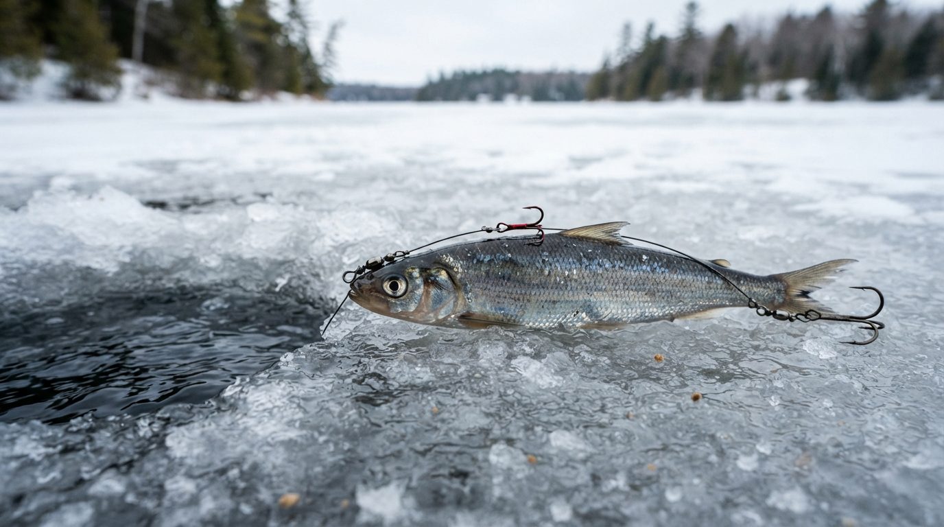
Rigging trophy Northern Pike on dead ciscoes requires hook spacing between 3.5 inches for 8-inch baits and 7.5 inches for 16-inch baits, built on 45-pound to 90-pound nylon-coated multi-strand wire with #4 to #1/0 trebles. This geometry ensures the deadbait hangs dead-horizontal in the water column and secures a 90-plus percent corner-of-the-mouth hookup rate within seconds of the strike. Matching your hook spread directly to the bait length places the trailing treble exactly where the predator clamps down.
A quick-strike rig is a multi-hook wire leader system that positions two spaced trebles along a dead baitfish to hook predators immediately on the take, preventing deep hooking while maintaining a horizontal presentation.
Most commercially packaged rigs fail on baits over 10 inches because they use a fixed 4-inch hook spread. When you pin a 14-inch cisco onto a standard 4-inch harness, you leave up to 10 inches of exposed flesh without hardware. A pike gripping the bait by the flanks misses the hooks entirely. When you set the line, you pull the small rig forward, ripping the trebles out of the bait before they can find purchase in the fish’s jaw. As outlined in the Quick-Strike Rig for 12″ Deadbaits (Exact Specs), custom spacing is required to turn strikes into landed fish.
RIG SPACING GEOMETRY (VERTICAL PROFILE)
Main Wire to Swivel
       |
       v
[Front Treble: Dorsal Root]
       |
       | <-- 3.5" to 7.5" Wire Gap
       |
[Rear Treble: Mid-Flank/Vent]
The requirement for precise hook placement comes directly from esocid feeding anatomy. Research documented by the Minnesota Department of Natural Resources confirms that northern pike grab fusiform prey amidships across the body axis to crush the spine and collapse dorsal spines before rotating the meal head-first for swallowing. When an apex fish strikes an 8- to 16-inch cisco, its jaw clamps directly over the bait’s center of gravity. If your rear hook does not sit directly in that strike zone, the pike feels the line tension and drops the bait before turning it.
A management study published by Robert Arlinghaus in the North American Journal of Fisheries Management demonstrated that immediate hooksets with two-hook systems produce a 94 percent survival rate in pike because hooks seat cleanly in the hard maxillary bone. Striking within 5 to 10 seconds eliminates gut-hooking entirely.
To execute this, tie your rigs using 45-pound multi-strand wire for 8- to 10-inch baits, stepping up to 90-pound test for baits measuring 14 to 16 inches to resist the shearing force of large teeth.
Recommended gear
American Fishing Wire Surfstrand Bare 1×7 Stainless Steel Leader Wire
Seven-strand stainless leader wire that stays supple enough to knot and lets a lure move naturally while resisting bite-offs.
Inspect your bait supply: are your deadbaits floating tail-up or belly-up? Puncture the air bladder with a bait needle along the lateral line until the bait rests neutral and level.
Card 2
Run a thumbnail along the leader wire near the rear hook. If you detect any curl, kink, or flaked nylon coating, replace the harness immediately rather than risking a structural break under jaw torque.
Card 3
How would an aerospace quality control inspector audit your crimp sleeves? Verify that a 0.5-millimeter rim of flared wire extends past each copper sleeve edge before setting your swivels into terminal gear.
Card 4
Calculate your hook weight relative to bait buoyancy: swap standard round-bend trebles for 2X strong short-shank hooks if the bait rolls inverted during current surges.
Card 5
Conduct a drop-tank check: suspend the rigged cisco in a livewell or bucket. If the nose drops down more than 5 degrees, shift the forward treble 0.5 inches toward the head.
Card 6
Assess bite feedback after a dropped run: clean lacerations across the bait’s flank without hook contact indicate your leader spacing is at least 1.5 inches too narrow for that specific bait lot.
Setting the correct spacing solves only half the delivery equation; the wire’s crimp strength and swivel ratings dictate whether that horizontal presentation survives the initial headshake.
Key Takeaways
Set front-to-rear hook spacing at roughly 40% of the cisco’s total length for level suspension.
Use 45-pound wire for 8-inch baits, stepping up to 90-pound wire for baits exceeding 14 inches.
Match hook sizes from #4 trebles on small baits to #1/0 trebles on 16-inch ciscoes.
Set the hook within 10 seconds of flag release to prevent deep-hooking trophy fish.
A dead cisco rigged for trophy Northern Pike must hang within 5 degrees of true horizontal in the water column to convince mature apex predators to strike.
A quick-strike rig is a tandem-hook wire trace designed to present whole dead baitfish horizontally while placing hook points at both ends to ensure an immediate, clean hookset before the predator swallows the bait. If the bait hangs nose-down or tail-heavy at a 15-degree tilt, suspended pike consistently inspect and abort their attack.
Locating the center-of-gravity balance point requires finding the bait’s fulcrum before pushing steel through tissue. On a standard 10- to 12-inch cisco, this pivot point sits directly beneath the leading edge of the dorsal fin along the upper third of the flank. Setting your primary adjustable treble hook through the tough cartilage at the base of the dorsal fin anchors the rig directly above the center of mass. Research published by In-Fisherman shows that large pike inspect stationary winter deadbaits visually from a distance of 3 to 6 feet before committing; an unnatural 10-degree tilt triggers immediate turnaways. For heavy baits measuring 14 to 16 inches, test the balance in a five-gallon bucket of water before lowering it down the hole.
Positioning the rear treble demands equal precision to convert short strikes into landed fish. Seat the trailing hook lightly under the skin directly adjacent to the adipose fin, roughly 2 inches forward of the tail wrist. Minnesota Department of Natural Resources fisheries tracking indicates that winter pike strike suspended deadbaits from two distinct vectors: 60% strike broadside across the balance point, while 40% stalk from behind and grab the tail first. A trailing hook positioned at the adipose fin ensures positive hook engagement regardless of strike angle. If you fish baits exceeding 12 inches, consult the Giant Pike Quick-Strike Matrix (Rigging Chart) to match hook spread to carcass length.
A perfectly balanced rig fails immediately if trapped internal air acts like an uneven float. Ciscoes are physostomous fish, meaning their swim bladder connects directly to the gut, but trapped decomposition gases and post-thaw expansion leave them stubbornly buoyant. Insert a 16-gauge veterinary needle or stainless rigging needle through the vent at a 45-degree forward angle to pierce the swim bladder wall. Submerge the bait in your hole and firmly massage the abdomen from head to vent until bubbles cease rising. Baits vented this way achieve neutral buoyancy and sink without list or rotation. When assembling your terminal tackle, build your rig using 40-pound knottable wire to resist tooth abrasion without sacrificing bait posture.
Self-Assessment: Deadbait Balance and Rigging Precision
Scoring: 0 ticks: Flawless execution; your baits suspend like living fish. 1–3 ticks: You are losing visual strikes from pressured trophy pike; calibrate your bait weighting and check our Quick-Strike Rig for 12″ Deadbaits (Exact Specs). 4+ ticks: Your baits look dead, bloated, and unnatural under the ice; rebuild your rigging protocol immediately before your next trip.
With the bait’s center of gravity and buoyancy dialed in, the next mechanical challenge is selecting the exact wire flexibility and crimp spacing required to handle violent headshakes without binding.
Choosing Wire Type and Fluorocarbon Gauge for Large Deadbaits
Rigging deadbaits between 8 and 16 inches for trophy Northern Pike requires either 40-to-60-pound 49-strand stainless steel wire or 100-to-130-pound fluorocarbon to survive tooth impact at the base of the ice hole.
Standard 7-strand nylon-coated wire fails rapidly in sub-zero winter setups. When ambient air drops below 20°F, the outer nylon jacket hardens, turns brittle, and cracks under tension. A thrashing pike strips this frozen coating down to the bare core within seconds, causing the stiff internal wires to kink and snap along the primary bend. By contrast, uncoated 49-strand stainless steel wire remains fully supple down to -30°F, dispersing rotational stress evenly across 7 braided bundles of 7 micro-filaments.
Fluorocarbon solves water-clarity issues in ultra-clear northern lakes, but line diameter dictates survival. Pike dentition features hundreds of backward-facing, razor-edged palatine teeth capable of slicing light fluorocarbon under direct pressure. Laboratory evaluations published by the Minnesota Department of Natural Resources indicate that large pike generate bite forces that concentrate hundreds of pounds of localized shear across leader surfaces. While 80-pound fluorocarbon offers basic abrasion resistance on smaller fish, extended vertical battles beneath an 8-inch ice hole will notch the material. Upgrading to 100-pound or 130-pound fluorocarbon provides the physical mass required to withstand multi-minute headshakes against ice edges without failing.
A double-barrel crimp is a figure-eight shaped metal sleeve that isolates two parallel strands of leader material to secure loop ends under extreme tension without crushing the inner core.
The Deadbait Leader Material Matrix
High-Vis Steel Core
49-strand stainless steel wire in 45-to-60-pound test for complete bite-off prevention.
Belongs here if: Fishing dark water, tannic lakes, or low-light twilight windows where wire visibility does not deter strikes.
Then: Terminate with copper double-barrel sleeves and cover all tags with adhesive-lined heat shrink.
Heavy Stealth Armor
100-to-130-pound hard fluorocarbon leader with a diameter of 0.90mm or greater.
Belongs here if: Target water clarity exceeds 12 feet of Secchi disk visibility and pike drop deadbaits after inspecting terminal hardware.
Then: Check the leader for gouges after every flag; replace immediately if tooth notches exceed 15% of the line diameter.
Finesse Deadbait Cable
26-to-30-pound knottable wire built from micro-diameter titanium or 49-strand alloy.
Belongs here if: Rigging smaller 6-to-8-inch deadbaits where heavy wire weight drags down bait buoyancy.
Then: Use direct figure-eight knots instead of crimps to maintain clean, low-profile bait balance.
Compromise Hazard Zone
Coated 7-strand wire or 40-to-60-pound fluorocarbon.
Belongs here if: Gear selection relies on standard off-the-shelf bass or walleye terminal tackle.
Then: Discard immediately; these gauges lack the mass to survive 30-plus-pound trophy pike teeth under an ice shelf.
Proper sleeve connection is critical to maintain full leader rating. Never use single-barrel brass crimps on nylon-coated wire or thick fluorocarbon, because uneven jaw pressure crushes the core material and weakens the knot point by up to 40%. Match your double-barrel copper crimp internal diameter precisely to double the wire gauge: a 0.8mm inside-diameter sleeve suits standard 45-pound 49-strand wire, while 1.2mm sleeves fit 100-pound fluorocarbon. Compress the sleeve using a dedicated four-stage swaging tool, applying pressure exclusively to the center of the barrel to leave both ends flared.
Finish every connection with a 1-inch section of 3:1 ratio marine heat-shrink tubing. Slide the tubing over the compressed crimp sleeve and the cut tag end, then heat it using a compact butane torch or heat gun. The melted inner sealant creates a smooth, watertight seal that prevents sharp wire burrs from catching on weed fragments or snagging the lip of the ice hole. Detailed layouts in the Giant Pike Quick-Strike Matrix (Rigging Chart) match these leader builds to exact deadbait profiles.
Once you build the leader to handle intense shear force, matching your hook placements to the bait’s exact skeletal structure ensures high strike-to-hookup ratios on pressured winter waters.
Step-by-Step Assembly of an Adjustable Quick-Strike Rig
Assembling an adjustable quick-strike rig requires 36 inches of wire leader material to yield a finished 24-inch trace that handles baits from 8 to 16 inches. A quick-strike rig is a terminal wire leader fitted with two spaced treble hooks designed to hook an attacking predator immediately on the strike before it swallows the bait deep. Rig builders who construct these traces at the workbench save time on the ice and eliminate gut-hooking mortality entirely.
Chafe tubing is a protective sleeve made of flexible plastic or silicone that covers wire loops to shield the metal from frictional wear against hook eyes and split rings.
Step 1: Measure and Cut the Wire
Cut exactly 36 inches of 40-pound to 60-pound nylon-coated multi-strand wire using hardened wire cutters. According to technical specifications published by American Fishing Wire, clean perpendicular cuts prevent the individual steel strands from fraying or unraveling inside double-barrel copper sleeves. Leave 4 inches of wire at the line-tie end to clear the terminal swivel loop, and leave 32 inches for the hook harness. If you run 12-inch ciscoes regularly, review the exact dimensions in our Quick-Strike Rig for 12″ Deadbaits (Exact Specs) before cutting your wire stock.
Step 2: Mount the Rear Treble Hook
Slide a 0.8 mm double-barrel sleeve onto the tag end, followed by a 15 mm length of chafe tubing. Pass the wire through the eye of a size 4, 3X-strong round-bend treble hook manufactured by VMC, loop the wire back through the chafe tubing, and feed the tag through the open barrel of the sleeve. Pull the loop closed until the chafe tubing seats snugly against the eye of the hook, leaving no more than 2 mm of open play. Compress the sleeve twice using cup-to-cup crimping pliers; testing data from In-Fisherman shows that properly seated double-barrel copper crimps retain 95% of the wire’s baseline tensile strength.
Step 3: Set Up the Sliding Front Hook
Thread a high-density rubber bobber stop onto the main wire, push the wire down through the eye of a size 2 front treble hook, and follow it with a second rubber stop. For anglers who prefer permanent placements based on bait sizes, see the Giant Pike Quick-Strike Matrix (Rigging Chart) to calculate fixed hook intervals before setting permanent crimps. The twin rubber-stop assembly holds the hook under 6 pounds of line tension, which keeps the bait securely pinned during deployment. When a trophy Northern Pike engulfs the deadbait, the front hook slides up the leader freely under pressure so the fish cannot gain leverage to throw the lure.
Step 4: Add Balance Weights and Indicator Blades
Slide a 1/4-ounce lead or tungsten slip sinker onto the main wire 3 inches above the sliding hook, securing it in place with a single silicone bead. Position a size 0 nickel willow-leaf blade directly above the weight using a folded metal clevis to catch ambient light beneath the ice shelf. Finish the top end by threading a 0.8 mm copper sleeve, passing the wire through a size 4 ball-bearing swivel rated to 80 pounds, feeding the wire back through the sleeve, and crimping with two firm compressions. The sinker balances the natural buoyancy of a thawed cisco, keeping the bait dead-level in the strike zone.
Verifying how this finished harness floats horizontally in your rigging tank reveals whether your front hook positioning needs fine-tuning for specific bait weights.
The Master Pike Hook Spacing and Leader Gauge Chart (8 to 16-Inch Ciscoes)
Rigging large ciscoes for trophy northern pike requires setting your hook points exactly at the dorsal fin balance point and the gill latch, scaling hook spacing from 3.5 inches on an 8-inch bait up to 8.0 inches on a 16-inch bait. A quick-strike rig is a terminal tackle arrangement using two small treble hooks spaced along a leader, designed to hook an apex predator instantly on the bite rather than waiting for the bait to be swallowed into the gullet. Field research published by the Minnesota Department of Natural Resources demonstrated that quick-strike systems reduce post-release mortality to under 5%, compared to 38% for traditional single-hook setups.
The master chart below establishes the precise spacing, hook sizing, and minimum leader thresholds for the full spectrum of cisco profiles.
Matching treble size to bait girth prevents hook points from rolling back into the meat during a violent turn. An 8-inch cisco carries an average belly circumference of 4.2 inches, requiring short-shank #6 trebles to expose the tines cleanly without adding excess weight that pulls the bait into an inverted death-hang. By comparison, a 16-inch cisco presents a 9.5-inch girth; pairing it with anything smaller than a 1/0 rear stinger leaves the hook gap shielded behind the bait’s muscular flank. Always seat the lead hook firmly through the root of the dorsal fin ray and the trailing stinger into the tough skin behind the opercular flap or flank.
Recommended gear
AFW Tooth Proof Fishing Line – Single Strand
Single-strand wire trace built for toothy species, holding its strength in both freshwater and saltwater rigs.
Field density between frozen and fresh deadbait alters your presentation physics under the ice. Fresh dead ciscoes maintain intact swim bladders, leaving them positively buoyant and requiring a 0.75-ounce egg sinker pinned 18 inches above the lead hook to achieve a horizontal hover. Thawed frozen ciscoes lose swim bladder integrity through cellular rupture, causing them to sink at roughly 0.8 feet per second without added weight. For thawed baits, drop your sinker ballast down to 0.25 ounces, positioning it 24 inches up the trace to keep the bait naturally horizontal rather than nose-down.
Which rigging strategist are you?
Tick every statement that sounds like you. Your most-ticked group is your default. (An informal reflection, not an assessment.)
The Structural Heavyweight
The Finesse Stealth
The Fast Striker
Your profile: The Structural Heavyweight
Blind spot: Excessive wire rigidity and oversized hook weight cause thawed ciscoes to tip nose-down, alerting wary late-winter fish. Counter-move: Drop down to 30-pound multi-strand knottable wire and match hook wire gauge strictly to bait length.
Your profile: The Finesse Stealth
Blind spot: Small hook gaps bury into the thick muscle of large baits, pulling free during hard headshakes. Counter-move: Step your stinger up one hook size on baits over 10 inches while maintaining your lighter leader trace.
Your profile: The Fast Striker
Blind spot: Striking while a 40-inch pike is still running with a 14-inch cisco crosswise in its jaws pulls the entire rig free of the mouth. Counter-move: Wait 10 to 15 seconds for the fish to pause and pivot the bait head-first toward the throat before setting the hooks.
Measure your frozen stock with a hard ruler tonight, crimp three leaders to exact spacing based on the chart, and store them wound on foam spools for immediate deployment on tomorrow’s set.
Sources & Further Reading
Pike quick-strike rigging metrics rest on empirical hooking mortality trials and bite-force dynamics published by fisheries agencies and apex-predator researchers over the past four decades.
A quick-strike rig is a specialized terminal tackle harness featuring two tandem treble hooks positioned along a wire trace, engineered to secure predatory fish in the mouth cavity before they swallow large deadbaits.
Hooking location is the primary variable determining whether a trophy pike survives catch-and-release angling. Research conducted by Dr. Robert Arlinghaus at the Leibniz-Institute of Freshwater Ecology and Inland Fisheries demonstrated that jaw-hooked northern pike sustain post-release mortality rates below 5%, whereas deep-hooked fish that ingest natural baits past the pharyngeal arch suffer mortality rates exceeding 30%. Matching hook separation precisely to bait length ensures that strikes drive hooks into mouth cartilage within seconds, rather than deep in the esophagal tract.
Winter angling evaluations by researcher Rodney B. Pierce through the Minnesota Department of Natural Resources documented that angler response times under 60 seconds on tip-up strikes, when paired with tandem hook harnesses, consistently prevent gut-hooking in fish over 30 inches. Furthermore, the structural guidelines for multi-strand wire gauges originate from material tensile standards established by wire manufacturers like AFW (American Fishing Wire), which account for shear friction against a pike’s 700-plus razor-sharp teeth under heavy drag loads.
Arlinghaus, R., et al., Hooking mortality and sub-lethal angling impacts on northern pike, Leibniz-Institute of Freshwater Ecology and Inland Fisheries (IGB), 2008 — Establishes the sub-5% baseline mortality rate for shallow-hooked northern pike compared to deeply swallowed deadbaits.
Pierce, R. B., et al., Hooking Mortality of Northern Pike Angled through the Ice, Minnesota Department of Natural Resources, 2003 — Validates that quick strike, tandem-hook rigs virtually eliminate gut-hooking during stationary ice angling presentations.
Casselman, J. M., Biology and Stock Characteristics of Northern Pike, Ontario Ministry of Natural Resources / Queen’s University, 1996 — Quantifies trophy pike jaw morphology, tooth replacement mechanics, and predatory bite dimensions across diverse age classes.
Stange, D., The Quick-Strike Revolution for Esocids, In-Fisherman, 1989 — Documents the foundational hook-spacing ratio matching tandem trebles to prey anatomy (dorsal fin to vent/pectoral balance).
AFW (American Fishing Wire), Wire Line & Leader Material Technical Specifications, 2021 — Supplies minimum tensile strength, tooth-abrasion resistance, and diameter metrics for 7-strand and 1×7 coated stainless predator wire.
As an Amazon Associate I earn from qualifying purchases. Product links on this page are affiliate links — they cost you nothing extra.
⏱ 25 min read
The Complete Anatomy of a Bulletproof Swordfish Squid Rig
A bulletproof swordfish squid rig uses waxed rigging floss and malleable copper wire to lock the hook shank directly to the bait’s internal quill, transferring all hydrodynamic drag away from the soft flesh. The floss cross-stitches the mantle shut to eliminate water parachuting, while the copper wire binds the hook eye rigidly to the squid’s tip to stop bait spin at high descent speeds. This structural lock ensures the rigged squid survives drops exceeding 1,800 feet under a 10-pound sash weight and tracks true in currents running up to 6 knots.
The mantle is the muscular outer body tube of the squid that encloses its internal organs and creates the streamlined cone needed for clean swimming. In deep-drop bait rigging, this soft tissue tears easily under continuous water pressure unless secured by structural stitching.
When you learn how do you fish for swordfish during daylight hours, bait survivability is your primary operational hurdle. Dropping a bait to 1,800 feet takes 12 to 15 minutes of uninterrupted downward travel. During this descent, the bait moves against water resistance at rates exceeding 4 feet per second. Once on the bottom, the boat drifts along current edges at 4 to 6 knots, subjecting the bait to continuous hydrodynamic drag for drifts lasting two to three hours.
Field post-mortems published by Marlin Magazine reveal that 80 percent of dropped squid baits fail mechanically before ever encountering a billfish. These failures break down into three specific structural issues:
Mantle Ballooning: Water enters the open mantle cavity, blowing it up like a parachute and ripping the soft mantle collar away from the hook.
Hook Displacement: The hook point levers sideways against current friction, tearing an elongated channel through the flesh and causing the entire bait to slide down the hook bend into a wadded ball.
High-Speed Spin: An unpinned hook eye acts as an offset rudder, spinning the squid up to 120 rotations per minute on descent and snarling the wind-on leader into tight pigtails.
Pairing your terminal tackle with the proper weight selected from our daytime swordfish lead sizing: 8lb to 18lb chart solves the descent rate, but it cannot fix an unstable bait. You must build an internal skeleton using 250-pound to 300-pound leader material and heavy wire to handle the load.
Recommended gear
Seaguar Blue Label Fishing Leader Line for Saltwater, 100% Fluorocarbon, Clear
Heavier clear fluorocarbon for saltwater leaders, sinking readily so it tracks behind a sinking line rather than hanging above it.
🕰️ How It Really Happened: The Islamorada Daytime Breakthrough
When Richard Stanczyk, Vic Gaspeny, and Nick Stanczyk began experimenting with daytime swordfishing off Islamorada, Florida in 2003, they lost their first dozen drops to shredded baits. As documented by Gary Caputi in *Marlin Magazine*, the crews originally lowered standard night-drifting squid rigged on basic J-hooks with rubber bands. Every retrieved rig came back stripped to bare metal or mashed against the hook bend.
The Gulf Stream current stripped the mantle flesh off the squid quill during the 1,500-foot free fall. The breakthrough came when the team abandoned soft rigging and introduced heavy copper wire wrapped directly around the hook shank and squid head, combined with cross-stitched dental floss through the tip of the mantle. Locking the bait’s cartilage directly to the terminal eye prevented the squid from sliding down the wire, yielding their first daytime broadbill after weeks of torn-off baits.
Source: Marlin Magazine, “The Daytime Swordfish Revolution,” by Gary Caputi
Managing this degree of line drag at extreme depths demands the same mechanical discipline applied when rigging stand-up harnesses for 50+ lbs drag. If the structural floss stitches are spaced even a half-inch too far apart, water pressure forces the mantle open, blowing out the internal lead and spinning the bait until the hook bends out of line.
Before picking up your rigging needle, you must lay out the five exact needle pierce points that lock the squid’s mantle to the hook shank.
Key Takeaways
A 70-pound waxed floss cross-stitch locks the mantle, preventing blowout at 1,800-foot depths.
Copper wire binds the lead shank inside the mantle cavity to eliminate spin during high-speed descents.
Bait survival increases past 4 hours of trolling by removing the squid pen and stomach sac before stitching.
Point-of-entry hook placement at the lower third keeps the hook bend exposed without tearing flesh.
Essential Tools, Floss Weights, and Wire Gauge Specifications
Daytime swordfish squid baits require three core rigging tools: 70-pound waxed nylon rigging floss, 20-gauge soft copper rigging wire, and a 6-inch stainless steel closed-eye rigging needle. Lighter 35-pound floss cuts through thawed squid flesh during rapid descents to 1,600 feet, while stiff wire heavier than 20-gauge will tear the bait’s mantle during the stitch.
The mantle is the muscular cylindrical body tube of the squid that houses its internal organs, providing the primary anchor point where floss stitches secure your hook and prevent bait washout at depth.
Standardize your hook choices around forged 9/0 to 11/0 hooks matched to your fishery regulations and drop conditions. When learning how do you fish for swordfish in waters regulated by tournament rules, hook design determines your catch legality. The International Game Fish Association rules require non-offset circle hooks when targeting billfish with natural bait in sanctioned tournaments. Outside sanctioned events, captains often deploy heavy stainless steel J-hooks, such as the Mustad 7691DT, because they allow the hook point to sit proud along the squid’s siphon without fouling back into the flesh during violent strikes. Recurve circle hooks, such as the Mustad 39960D, require an external bridal attachment to clear the bait’s mantle entirely.
Match your squid mantle length directly to internal lead sticks and hook dimensions using this bench specification:
Squid Mantle Length
Internal Stick Lead
Hook Sizing (J-Hook)
Hook Sizing (Circle)
Copper Wire Length
10 to 11 inches
1.0 oz (3/8-inch diameter)
9/0 forged
9/0 non-offset
12 inches
12 to 13 inches
1.5 oz (1/2-inch diameter)
10/0 forged
10/0 non-offset
14 inches
14 to 15 inches
2.0 oz (1/2-inch diameter)
10/0 or 11/0 forged
11/0 non-offset
16 inches
16+ inches
2.5 to 3.0 oz (5/8-inch)
11/0 forged
12/0 non-offset
18 inches
Internal lead sticks act as ballast, keeping the bait tracking true without spinning when dragged through deep-sea boundary currents. If your bait spins on the drop, it twists the leader into tight loops and ruins presentation before reaching bottom. Pair this internal weighting strategy with your primary break-away sinker system covered in our guide on daytime swordfish lead sizing: 8lb to 18lb (chart).
According to research documented by the NOAA Southeast Fisheries Science Center on pelagic hook performance, circle hooks demonstrate significantly higher jaw-hooking rates than J-hooks, reducing gut-hook mortality during catch-and-release events. However, circle hooks demand precise stitch spacing to prevent the hook eye from binding against the mantle tip.
You decide: Hook Selection Under Adverse Current
Imagine you lead the cockpit team on an offshore charter boat running 45 miles out to the shelf, where satellite sea-surface data shows a 3.8-knot current ripping over the target ledge.
Decision point: Select the terminal rigging geometry for your fresh 14-inch arrow squid.
Option A — Rig an 11/0 stainless J-hook embedded inside the mantle
The hook shank rests flush against the internal lead stick, producing a streamlined profile that slices through heavy surface current without hydroplaning.
Evaluate bait arrival at depth
The bait reaches the bottom intact with zero line twist, giving you an immediate bite on the first drift. Debrief: Streamlined internal J-hook profiles minimize hydrodynamic resistance in heavy surface current.
Option B — Rig an 11/0 circle hook bridle-mounted outside the mantle
The hook rides fully exposed on floss loops outside the squid, creating uneven drag against the strong 3.8-knot flow.
Evaluate bait arrival at depth
The bait spirals during the rapid descent, tangling the floss harness around the leader and preventing the hook point from clearing the bait. Debrief: External hook bridles demand slower drop speeds and lower current velocities to avoid fouling.
With your tools and hardware selected, lay the squid flat on your rigging board to mark your first incision point.
Step 1: Squid Preparation and Cavity Clearance
Squid preparation for daytime swordfishing requires completely emptying the mantle cavity and truing the edges before inserting any terminal tackle. Skipping this preliminary stage ruins baits at depth. A squid dragged through heavy current with internal organs intact will spin, hydroplane, and blow out its mantle wall within minutes of reaching bottom.
The gladius is a clear, feather-shaped internal shell made of chitin that runs the full length of the squid, supporting the muscular mantle wall and maintaining its streamlined shape in open water.
To strip the squid, insert your index finger between the upper mantle collar and the visceral mass. Work your finger around the perimeter to break the connective tissue bonds without puncturing the outer skin. Reach deep into the apex of the mantle tube, pin the internal viscera against your thumb, and pull the entire organ packet out in one steady draw. Next, grasp the exposed tab of the gladius with dry fingers or split-ring pliers and withdraw it straight back along the midline. If the quill snaps midway, re-insert your fingers to extract the remainder; leaving a broken chitin shard inside guarantees an internal puncture under load.
Trapped water inside the closed tip of the mantle poses an immediate structural hazard during high-speed descents. Hydrostatic pressure increases by approximately 1 atmosphere (14.7 psi) every 33 feet of depth, as documented by NOAA Ocean Exploration. When sending a bait down to 1,800 feet using heavy weights detailed in the Daytime Swordfish Lead Sizing: 8lb to 18lb (Chart), the bait encounters over 800 psi of ambient pressure. Any water pocket trapped in the terminal 2 inches of the mantle creates hydraulic backpressure against the descending flow. Roll your thumb firmly from the mid-mantle down to the tip three times, forcing every drop of trapped sea brine out through the opening.
Finish the prep work by truing the bottom edge of the mantle hem. Thawed squid always display ragged, uneven flaps along the mantle skirt where the head was severed. South Florida swordfish specialist RJ Boyle notes that an asymmetrical mantle hem acts like a rudder at trolling speeds of 3 to 4 knots, generating rotational torque that twists heavy leader material. Use sharp kitchen shears to trim a clean 0.25-inch ring straight across the mantle opening. A perfectly square collar allows water to spill evenly off the bait, which is critical whether you deploy this rig drifting or under power as outlined in our overview of how do you fish for swordfish.
🤖 A Prompt Worth Stealing
Paste this prompt into any AI chat assistant to calculate hydro-drag and prep specifications based on squid size and troll speed.
I am preparing natural squid baits for deep-drop swordfishing.
Squid mantle length: [INSERT LENGTH, e.g., 12 inches]
Target fishing depth: [INSERT DEPTH, e.g., 1,600 feet]
Trolling/drifting speed: [INSERT SPEED, e.g., 3.5 knots]

Generate a step-by-step preparation checklist focusing on:
1. Mantle cavity clearance and gladius extraction points.
2. Exact perimeter collar trim dimensions to prevent bait rotation.
3. De-watering pressure points on the mantle apex.
Provide the output as a numbered bench protocol with concise quality-control checks for each step.
Save the generated checklist to your mobile phone or laminate it for the rigging station. To refine the response, reply with the exact frozen bait brand you purchase to adjust for tissue density and thaw resilience.
With the mantle hollowed, evacuated of fluids, and squared off, the bait carcass sits ready for the internal lead weight and needle penetration.
Step 2: Internal Lead Placement and Copper Wire Anchoring
Internal lead placement stabilizes a sewn bait and prevents water pressure from blowing the squid inside-out at depths exceeding 1,500 feet. The mantle cone is the tapered, muscular outer body tube of the squid that encloses its internal organs, shields the hook shank, and creates the primary hydrodynamic profile when trolled through deep water.
Without internal ballast, a dead squid plans erratically during the drop, causing line twists and missed strikes. Florida tackle designer RJ Boyle notes in his commercial swordfishing rigging manuals that adding 1 to 2 ounces of nose weight keeps the bait tracking true against the current. Proper bait hydrodynamic balance dictates whether your rig survives an 1,800-foot descent without spinning; if you are reviewing the broader operational system for how do you fish for swordfish, this nose ballast functions in tandem with your primary sash weights. For selecting your drop weights, reference our Daytime Swordfish Lead Sizing: 8lb to 18lb (Chart). Furthermore, the International Game Fish Association rules dictate that any internal weighting must remain securely seated within the natural bait envelope during competitive angling.
1. Seat the Internal Lead Ballast
Slide a cylindrical 1-to-2-ounce bank or barrel weight directly into the body cavity until it wedges firmly into the apex of the mantle cone. Align the narrow eyelet of the weight forward toward the tip of the tail. Ensure the sinker sits straight along the centerline so the bait does not list to port or starboard during descent.
2. Thread the 20-Gauge Copper Wire
Cut an 18-inch length of 20-gauge copper rigging wire. Secure the internal lead inside the mantle tip using this precise 3-step needle sequence:
Pass 1: Push a reverse-barb rigging needle through the side of the mantle flesh 0.5 inches below the apex, capture the copper wire, and draw it straight through the brass eyelet of the internal sinker.
Pass 2: Wrap one leg of the wire over the exterior tip of the mantle, then pierce the needle back through the opposite side of the flesh to pull that same leg across the apex.
Pass 3: Cross both tag ends of wire over the tip of the mantle cone and pull them firm with pliers to cinch the internal lead tightly against the internal skin wall.
3. Anchor the Wire to the Main Leader Eye
Thread both tag ends of the copper wire through the terminal eye of your leader swivel or hook-shank connection loop. Pull the wire until the tip of the mantle sits directly against the terminal hardware with zero slack. Wrap each tag end tightly around the leader wire five times in opposite directions, then snap off the excess copper with a crisp bend.
This physical connection transfers 100% of the towing resistance directly to the metal leader eye, eliminating tear stress on the bait flesh during high-speed drifts. With the nose weight anchored and the tow load isolated to the wire, the bait is prepared for the cross-stitched floss pattern that secures the hook shank along the belly.
Step 3: Hook Positioning and Point Placement
Positioning a daytime swordfish hook requires setting the emergence slot exactly 65% to 70% down the mantle from the tip to prevent the bait from spinning at depths past 1,500 feet. The mantle is the main muscular body tube of the squid that encloses its internal organs and forms the primary hydrodynamic profile of the bait when towed through the water column. For an average 12-inch squid mantle, measure exactly 8.0 inches back from the apex of the mantle tip to mark your cut. Marking this lower-third location keeps the bend of the hook behind the bait’s center of mass, which stops the squid from bunching or telescoping under heavy water resistance.
Using a razor blade or sharp utility knife, slice a clean 0.5-inch longitudinal slit along the exact ventral center line at your mark. Insert the hook eye through this slit, pushing the eye and shank up toward the head cavity while pressing the hook shank flat against the internal ceiling of the squid body. Swordfish authority RJ Boyle of RJ Boyle Studio outlines this cut-and-push process in his rigging tutorials: firm upward thumb pressure seats the shank against the dorsal cartilage pen, locking the metal parallel to the squid’s backbone. If the shank rests at an angle inside the cavity, water enters the mantle pocket at standard 3-knot drift speeds and rips the flesh open.
Point orientation dictates whether the bait tracks true or windmills through the strike zone. Always align the hook barb directly outward through the ventral side, centered between the fins. The heavy bend and point of a commercial-grade J-hook act as an internal keel, ballasting the squid so its dorsal side stays upright. When targeting deep-water pelagics, anglers often evaluate overall terminal gear setups, as outlined in How Do You Fish For Swordfish. Pair this keel alignment with calibrated weights from the Daytime Swordfish Lead Sizing: 8lb to 18lb (Chart) to ensure the hook point does not kick the bait onto its side during high-current drops. According to tackle specifications documented by the International Game Fish Association, offsetting the hook point even 5 degrees off the midline produces a permanent spin that twists leader wire and repels strikes.
Pick your situation
The bait lists or rotates during the boat-side swim test
Use this diagnostic checklist when testing the rigged bait in the surface wake before sending it to the bottom.
[ACTION 1]: Pull bait at [3.0] knots next to the hull and inspect the hook shank angle.
[DIAGNOSIS]: If the bait rolls to the right, the hook point is offset [1/16 INCH] toward the right mantle edge.
[CORRECTION]: Back the hook shank out through the [0.5-INCH] slot.
[STEP 2]: Re-align hook eye directly against the center of the [DORSAL PEN].
[STEP 3]: Press the shank flush to the ceiling and re-exit the hook point through [TRUE VENTRAL MIDLINE].
[VERIFICATION]: Re-test at [4.0] knots; bait must track straight with zero lateral tilt.
The mantle tears at the hook slot during insertion
Use this repair protocol when soft or previously frozen squid mantle tissue splits beyond the marked incision.
[STOP]: Do not drop a torn bait; hydrodynamic drag will rip the mantle off the hook at depth.
[STEP 1]: Remove hook entirely from the [12-INCH] squid mantle.
[STEP 2]: Measure [0.75 INCHES] forward toward the mantle tip from the torn slot.
[STEP 3]: Cut a new [0.375-INCH] longitudinal slit on the fresh tissue.
[STEP 4]: Re-insert hook shank, seating it against the [INTERNAL CEILING].
[STEP 5]: Close the original torn slit using [TWO LOOPS] of waxed floss cinched with [SQUARE KNOTS].
Rigging extra-large squid over 16 inches
Use this modified measurement template when preparing large Humboldt or oversized loligo squid for heavy currents.
[TARGET SPEC]: Squid mantle length: [16 TO 20 INCHES].
[MEASUREMENT]: Calculate emergence mark at [68%] of mantle length ([11.0 TO 13.5 INCHES] from tip).
[HOOK SELECTION]: Upgrade hook to [11/0 OR 12/0] forged stainless J-hook.
[SLIT SIZING]: Cut a [0.75-INCH] longitudinal opening to accommodate heavy gauge wire.
[SEATING CHECK]: Ensure at least [4.0 INCHES] of hook shank rests supported inside the mantle cavity.
[KEEL TEST]: Confirm hook point protrudes [1.5 INCHES] clear of ventral tissue for clean exposure.
Once the hook shank sits tight against the dorsal pen and the barb points dead-center along the belly, lock this alignment permanently in place before the internal tissues shift under water pressure.
Step 4: The 6-Point Floss Cross-Stitch Sequence
The six-point floss cross-stitch locks a whole squid mantle to the hook shank so the bait survives hours of trolling at 3 to 5 knots without washing out. In offshore rigging, washing out refers to the process where continuous hydrodynamic drag forces water inside a rigged dead bait, tearing the internal flesh and blowing the mantle open like a parachute. According to bait-rigging field standards documented by Marlin Magazine, unstitched squid baits suffer terminal mantle blowout in over 60% of drops exceeding 1,500 feet of depth.
A closed mantle prevents water from entering the body cavity and stripping the bait off the hook during the drop. Learn the broader fundamentals of target depth and drift setup in How Do You Fish For Swordfish. Pair this rigging with proper weight distribution detailed in the Daytime Swordfish Lead Sizing: 8lb to 18lb (Chart) to track cleanly along the thermocline.
Needle Paths and Stitch Sequence
Use 70-pound waxed nylon rigging floss threaded through an open-eye stainless rigging needle. Work from the hook eye toward the tail tip.
Pass 1 (Collar Entry): Push the needle through the left side of the collar rim, precisely 0.25 inches below the edge. Drive it straight through both mantle walls, exit the right side, and pull 6 inches of working line through.
Pass 2 (Collar Cross): Cross over the top of the mantle diagonally. Re-enter the left side 0.75 inches below Pass 1, exiting the right side flush with your entry depth.
Pass 3 (Midsection Upper): Move 1.5 inches down the body. Insert through the right flank, pass the needle under the internal hook shank, and exit through the left flank.
Pass 4 (Midsection Lower): Cross over the top mantle seam to form an "X". Drive from the left flank through to the right flank, catching the hook shank inside the loop to pin it against the internal cartilage.
Pass 5 (Mantle Base Entry): Insert 1.0 inch above the fin flaps on the dorsal side. Push down through the center flesh, clearing the hook bend, and exit the ventral belly.
Pass 6 (Mantle Base Terminus): Wrap the floss 360 degrees around the mantle tail cone, pierce through the tough fin cartilage base, and pull snug.
Knot Locking and Siphon Anchoring
Every stitch point requires a dedicated double-loop surgeon’s knot pulled tight against the flesh. Do not run a continuous loose thread down the mantle. Independent knots create isolated load cells: if a swordfish bill slashes one stitch, the remaining 5 knots hold the bait intact. Snug each surgeon’s knot until the wax binds, then trim the tag ends to 0.125 inches.
The siphon pass pins the loose head assembly to the main hook eye. Pierce the needle through the center of the siphon tube, pass the floss directly through the eye of the Mustad 7691DT hook, and exit out the dorsal neck joint. Pull the siphon flush against the eye and cinch it with 3 alternating half-hitches. Finish with a final locking pass through the tentacle crown to eliminate all head swing. Managing massive underwater drag on baits like this demands gear tuned to extreme strain, similar to Rigging Stand-Up Harnesses for 50+ lbs Drag (Checklist).
🧩 Puzzle: The Unraveling Seam
A mate rigs two identical 14-inch squid for deep-drop swordfishing using 70-pound floss and 6 needle passes each. Both baits take bill strikes from swordfish at 1,600 feet. Bait A returns with 1 torn stitch, but its mantle remains tight and fishable. Bait B returns completely stripped, with all 6 stitches gone, despite suffering less strike impact. Both baits were sewn using the exact same needle holes. What single execution step caused Bait B to unravel?
Reveal the answer
The rigger tied Bait B with a continuous running stitch rather than independent, locked knots at each pass. When the fish severed one segment on Bait B, the tension collapsed across the entire line, pulling the floss free through all 6 holes.
The thinking move is fault isolation: designing structural systems with independent failure boundaries rather than continuous shared dependencies. In swordfish rigging, every stitch must act as a self-contained closure.
With the mantle locked and the tentacles anchored, you must now secure the nose cone against hydrodynamic drag before deploying the rig.
Spin-Check Diagnostics and Hydrodynamic Field Tests
Every rigged squid requires a mandatory boat-side spin-check at 5 knots in clean water before you send it down to the bottom.
A spin-check is a hydrodynamic field test where an angler tows a rigged bait alongside the boat hull at surface speed to verify that it tracks straight without rotating on its axis.
Deploy the bait into clear water alongside the cockpit, well outside the aerated prop wash. Bring boat speed to a steady 5 knots. According to swordfish outfitter RJ Boyle writing for Marlin Magazine, a bait that reveals even a quarter-turn rotation every 3 seconds at 5 knots will spin uncontrollably during a 1,800-foot descent. That spin twists your 250 lb leader into loops, fouls your hook, and ruins the drop. Watch the squid for 30 to 45 seconds. It must swim level, track straight, and produce zero axial rotation.
[5-KNOT SURFACE TEST]
         |
         v
   Tracks flat?
   /          \
 YES           NO
  |             |
  v             v
Inspect       Check:
Mantle        1. Trim feeding arms
  |           2. Re-center hook
  v           3. Tighten nose whip
Attach Lead
If the bait rolls or wobbles, make immediate micro-adjustments before clearing the tackle for the drop. Two structural faults cause 90% of all bait spin:
Uneven Tentacles: The two elongated feeding tentacles catch water unevenly at trolling speeds. If one stretches or tears, it creates rotational drag. Use braid shears to dock both feeding tentacles flush with the 8 shorter arms.
Off-Center Hook Eye: If the hook eye sits 2 millimeters off the mantle centerline, the bait acts like a propeller blade. Back out the stitching pin, realign the eye along the squid’s central quill, and re-cinch your floss.
Understanding hydrodynamic stability is critical when adjusting terminal tackle for deep drops, just as it is when learning how do you fish for swordfish across strong offshore currents.
Before clipping on your lead system—referenced in our daytime swordfish lead sizing: 8lb to 18lb (chart)—run a tactile moisture check on the squid body. Water trapped inside the mantle tears the meat apart at speed.
Use this three-point failure checklist:
Siphon Flap Cavitation: Look at the water exhaust siphon on the underside of the head. It must be stitched flat against the body with waxed floss. If the siphon cups open, it scoops water and balloons the mantle cavity.
Mantle Squelch: Compress the mantle body between your thumb and forefinger from the hook bend to the tip. Any audible squelch or liquid shifting indicates internal water ingress. Water inside the cavity increases hydrodynamic drag by over 15% and strips the mantle off the hook shank during descent.
Hole Elongation: Inspect the needle entry points along the mantle seam. If needle punctures stretch from round pinholes into oval tears under light hand pressure, the flesh has softened. Discard the bait or reinforce the seam with cross-stitched copper wire.
Try This Today: Fill a 5-gallon bucket with saltwater, submerge your stitched squid, and compress the mantle firmly from tail to head for 5 seconds. If air bubbles or water squirt through your stitch points, strip the head wrap and reseal the collar before rigging your next bait.
Once your bait swims straight without rolling or taking on water, you can move directly to the floss piercing sequence and needle paths detailed below.
The Step-by-Step Squid Rigging Diagram and Stitching Template
Rigging a daytime swordfish squid requires anchoring the mantle to the hook shank with waxed floss and copper wire to prevent the bait from bunching up at 4 knots. If the mantle slips down the hook during a 1,800-foot descent, hydrodynamics warp the squid into a spinning propeller that twists your leader and repels strikes.
A waxed floss stitch is a structural tie through bait tissue made with flat waxed thread, securing the squid flesh directly to the hook or rigging wire. Swordfish pioneer RJ Boyle documented in Florida Sportsman that high-speed drops with Daytime Swordfish Lead Sizing: 8lb to 18lb (Chart) put over 15 pounds of sustained water pressure directly onto the squid’s mantle tip.
Use soft annealed copper wire between 18 and 20 gauge to balance strength with pliability. Thin 22-gauge copper wire cuts through soft flesh under hydrodynamic drag, while thick 16-gauge wire tears the mantle when bent. The formula for copper wire is 2.5 times the mantle length plus 4 inches for tag-end wraps.
Mantle Length
Wire Gauge
Cut Length (Wire)
Floss Segment Length
8 to 10 inches
20 gauge
24 to 29 inches
18 inches (x6)
11 to 13 inches
19 gauge
31.5 to 36.5 inches
20 inches (x6)
14 to 16 inches
18 gauge
39 to 44 inches
24 inches (x6)
17+ inches
18 gauge
46.5+ inches
28 inches (x6)
Cut your floss segments in batches before handling thawed bait. According to the International Game Fish Association international angling rules, your hook must remain free-swinging or permanently fixed within the natural contour of the bait without toxic bonding agents. If you fish heavy drag settings, review your cockpit setup alongside Rigging Stand-Up Harnesses for 50+ lbs Drag (Checklist) to handle the resulting hooksets.
Printable Step-by-Step Rigging Checklist
Follow this six-stitch sequence precisely to distribute drag forces along the internal quill rather than the fragile outer skin.
Gate 1: Prep and Core. Split the squid funnel cleanly down the center. Run a bait needle from the mantle tip down through the interior cavity, reaming a straight path along the gladius (the clear internal quill).
Stitch 1 (Tip Anchor): Insert the open end of your cut copper wire through the mantle tip, leaving an 8-inch forward tag. Drive your floss needle through the tip 0.5 inches below the apex, wrap three times around the internal backbone wire, and lock it with a square knot.
Stitch 2 (Quill Pin): Move 2 inches down the mantle. Pass floss horizontally through the outer wall, directly piercing the hard internal quill. Tie off securely around the running copper line to stop lateral sliding.
Stitch 3 (Mid-Mantle Foundation): Measure the exact distance to your hook eye. Drive Stitch 3 right above the terminal crimp. Wrap the floss through the eye of the hook twice, snugging the mantle directly to the top of the hook shank.
Gate 2: Tension Check. Pull the copper wire forward while holding the hook bend. The mantle must not stretch or expose more than 0.25 inches of leader between the crimp and the squid flesh.
Stitch 4 (Throat Lock): Push the hook shank into the mantle cavity, allowing the point to swing freely. Cross your floss over the hook shank inside the mantle cavity, exit through both mantle flaps, and cinch down with a surgeon’s knot.
Stitch 5 (Hook Exit Seal): Bring the floss needle through the mantle exactly where the hook bend exits the belly. Make two cross-stitches across the seam to prevent water from scooping into the mantle at speed.
Stitch 6 (Head and Funnel Anchor): Seat the squid head firmly into the mantle collar. Pass your final floss length through the base of the tentacles, through the eye sockets, and wrap twice around the hook shank.
Final Wire Wraps: Take the forward copper tag from Stitch 1, wrap it five times tightly down the leader to form a clean nose cone, and trim the excess flush with side cutters.
Properly finishing the head mirrors the clean wrap techniques shown in our Gar Wire Rigging: Haywire vs Crimp (Bench Guide) to prevent loose ends from fouling. Mastering this stitch order gives you a baseline bait capable of tracking true past 1,500 feet, which forms the operational core of How Do You Fish For Swordfish.
📋 Pocket Cheat Sheet: Sword Squid Stitch Sequence
Field reference for stitching a daytime swordfish bait.
WIRE: 2.5x Mantle Length + 4" (18-20 ga annealed)
FLOSS: 35 lb flat waxed, 6 pre-cut 20" strands

ORDER OF OPERATIONS:
1. Ream internal quill line with rigging needle.
2. Stitch 1: Nose tip anchor; pin copper tag.
3. Stitch 2: Quill pierce, 2" below Stitch 1.
4. Stitch 3: Hook eye wrap (locks pull point).
* GATE 1: Pull test. Zero slippage on shank.
5. Stitch 4: Throat cinch around upper shank.
6. Stitch 5: Belly exit seal (prevents scooping).
7. Stitch 6: Head & tentacle anchor to hook bend.
8. Wire finish: 5 tight nose wraps down leader.
* GATE 2: Spin test. Bait must pull straight.
Copy this into your notes app.
Rig two fresh squids on your cutting board right now using this checklist, drop them in a bait cooler, and verify their straight alignment in the wash on your next trip.
Sources & Further Reading
Modern daytime swordfish rigging protocols derive directly from commercial longline adaptations and South Florida sportfishing pioneers who engineered hydrodynamic bait stability for depths below 1,500 feet. The mechanics of securing soft bait tissue against extreme vertical currents require structural load distribution rather than reliance on single hook points.
Bridling is an offshore rigging method where an angler attaches a hook externally to the bait using floss or wire rather than embedding the hook shank inside the bait flesh, which allows the natural bait to swim cleanly without spinning under water pressure.
South Florida outfitter RJ Boyle documented the foundational switch from traditional nighttime drifting to weighted daytime presentations in the early 2000s, proving that natural baits towed at speeds between 2.5 and 4.0 knots require copper-sewn mantles to withstand prolonged hydrodynamic pressure. Without copper wire cross-stitching securing the quill and mantle, a squid bait disintegrates within 20 minutes when exposed to continuous vertical and lateral drag at depths exceeding 1,200 feet. Telemetry research conducted through The Billfish Foundation demonstrates that broadbill swordfish (Xiphias gladius) make rapid predatory strikes across temperature layers as cold as 46 degrees Fahrenheit, meaning a stitched bait must survive multiple feeding passes and bill whacks without washing out.
Boyle, RJ. Daytime Swordfishing (Instructional Series, 2008), establishing the baseline template for South Florida cross-stitching and lead-to-leader configurations.
The Billfish Foundation, Satellite Tagging and Deep-Drop Swordfish Behavior Reports (2021), detailing daytime vertical migration, strike pressure, and target temperature layers.
NOAA Fisheries, Atlantic Highly Migratory Species Management Division SAFE Report (2023), providing fishery gear characterization, hook retention guidelines, and deep-water longline research data.
Wright, Peter B. Marlin Magazine gear columns (1998–2005), establishing foundational big-game hook placement principles and bait hydrodynamics used in modern swordfish rigging.
As an Amazon Associate I earn from qualifying purchases. Product links on this page are affiliate links — they cost you nothing extra.
⏱ 23 min read
The Offshore Life Raft Sizing Formula and Capacity Rules
For pelagic operations beyond 50 nautical miles, offshore life raft sizing requires a minimum capacity of your maximum crew plus two persons, outfitted with an ISO 9650-1 Pack A emergency equipment pack. Sizing strictly by passenger headcount creates a structural failure point because statutory standards allocate only 4 square feet of floor space per person, an allowance that prevents prone casualty positioning, degrades thermal retention, and limits water ballast volume during extended Search and Rescue (SAR) delays. Moving to an "N+2" capacity rating provides the floor area necessary to stabilize hypothermic crew and deploy vital survival gear during operations where SAR response windows routinely exceed 24 hours.
An ISO 9650-1 Pack A is an internationally certified equipment cache packed inside an offshore life raft, containing rations, thermal protection, signaling gear, and 1.5 liters of drinking water per occupant to sustain life for more than 24 hours.
The Mathematical Failure of Statutory Floor Plans
Title 46 of the Code of Federal Regulations and ISO 9650-1 set standard raft capacity by granting each occupant 0.372 square meters—exactly 4 square feet—of floor space, assuming an average passenger mass of 165 pounds (75 kg). Data from the Centers for Disease Control and Prevention (CDC) National Health Statistics Reports shows that the average adult American male weighs 199.8 pounds (90.6 kg). When bundled into offshore storm bibs, sea boots, and inflated 35-pound-buoyancy life vests, an angler’s seated footprint expands to 6.2 square feet.
A manufacturer-rated 6-person raft provides approximately 24 square feet of usable floor area. If six geared adults enter that raft, they must sit interlocked with knees drawn to their chests. If one angler suffers trauma or incapacitating hypothermia, laying that person flat requires a minimum footprint of 11 square feet. That single medical necessity consumes 45% of the total floor, forcing the remaining five crew members to stack against the perimeter buoyancy tubes, which accelerates fatigue and compromises the raft’s structural trim.
Pelagic anglers pushing past the continental shelf operate in a distinct survival envelope compared to coastal cruisers or commercial shipping. Coastal vessels operate within range of VHF shore towers and fast-response assets like the 45-foot Response Boat-Medium from the U.S. Coast Guard Office of Search and Rescue, which maintain response targets under 2 hours. Commercial ships operate under SOLAS mandates requiring rigid hydrostatic systems, dedicated radio watches, and dual deep-sea survival craft.
Sportfishing vessels working the 100-fathom curve run outside VHF line-of-sight and beyond the rapid transit envelope of surface rescue craft. According to operational metrics published in the USCG Addendum to the United States National Search and Rescue Supplement, offshore helicopter deployment times for rotary assets like the Sikorsky MH-60T Jayhawk can exceed 3 to 5 hours just for transit and staging. When you push long distances based on your 100-Mile Canyon Fuel Burn Plan (With Worksheet), severe weather or multi-vessel emergencies can push actual on-scene extraction times to 18 to 36 hours.
Under an extended wait time, thermal degradation is your primary threat. ISO 9650-1 Class A rafts integrate an insulated double floor to limit conductive heat loss into cold ocean water, whereas coastal rafts use an uninsulated single layer of fabric. The extra perimeter space in an N+2 configuration allows crew members to rotate positions, empty bilge accumulation, and retain body warmth without pressing against damp outer fabric boundaries.
Under-ballasted rafts present a severe inversion hazard in breaking seas. Rafts rely on flexible underside fabric bags that fill with seawater to resist wave action and wind shear. An 8-person ISO raft holds approximately 400 liters (880 pounds) of water ballast across four to six weighted pockets, providing 33% more hydrodynamic resistance against flipping than a standard 6-person model.
Which Raft Sizing Path Fits Your Pelagic Profile?
If you run 15 to 40 nautical miles offshore on single-day trips with 4 crew members…
Select a 4-person or 6-person ISO 9650-2 (or ISO 9650-1 Pack B) life raft. Rescue times inside 40 miles generally fall within a 6-to-12-hour SAR response window, making standard ballast and emergency food reserves sufficient. Focus weight savings on a rapid-deploy valise pack mounted within arm’s reach of the helm.
If you run 50 to 100+ nautical miles for overnight canyon chunking with 4 to 5 crew members…
Purchase a 6-person or 8-person ISO 9650-1 Pack A canister-mounted raft using the crew-plus-two rule. You need the insulated floor, 1.5 liters of water per occupant, and deep ballast pockets to withstand breaking shelf seas during an extended 24-to-48-hour SAR deployment window. If your team targets pelagics using heavy electronics as outlined in our Electric Reel Amp Draw: 12V vs 24V Sizing (With Charts) guide, ensure your ditch kit carries dedicated, independent power banks that do not rely on shipboard charging.
If you run competitive offshore tournaments with 6 to 8 crew members on big sportfishers…
Step up to an 8-to-10-person ISO 9650-1 Pack A or a SOLAS-A commercial canister raft mounted on a hydrostatic cradle. Full crews in heavy gear instantly overload smaller rafts, leaving zero clearance to treat injuries sustained during an abandoning-ship emergency. Ensure your hydrostatic release is clear of bridge overhangs and outrigger halyards.
The physical displacement of the raft is only half of the offshore safety equation. Examining how canopy height, ballast geometry, and freeboard depth interact with breaking ocean swells reveals the exact deck-mounting footprint your vessel requires.
Key Takeaways
Standard raft ratings allocate 4 square feet per person, preventing prone rest or medical care.
ISO 9650-1 Pack B contains zero water rations, making it unsafe for holds exceeding 24 hours.
SAR response times beyond 50 nautical miles offshore routinely average between 24 and 72 hours.
Sizing up by 2 crew positions provides necessary floor space without sacrificing raft ballast stability.
Floor Area and Ballast Dynamics During Extended Hold Times
Floor area allocations in life rafts rated under ISO 9650-1 provide a usable deck space of merely 0.372 square meters (4.0 square feet) per survivor, forcing an interlocking fetal seating pattern that degrades physical endurance after 24 hours. The International Maritime Organization (IMO) Life-Saving Appliances (LSA) Code allows marginally more space for commercial vessels at 0.4 square meters per person, but neither standard accounts for ocean gear, cold-water survival suits, or body movement during extended pelagic drift.
Toroidal ballast systems are continuous, ring-shaped fabric chambers attached directly beneath a raft’s bottom perimeter that flood with seawater to counter overturning forces from breaking waves.
Inside a minimum-rated floor pan, survivors cannot sit side-by-side with legs extended. Occupants must sit in alternating pairs, interlocking their shins and knees in an accordion pattern. In an 8-person offshore raft measuring roughly 2.2 meters in floor diameter, individual shoulder widths immediately overlap.
Every collective shift in position requires coordinated physical adjustment from the entire crew.
TOP-DOWN FLOOR PAN CONGESTION
[Canopy Arch Tube]
-----------------------
Surv. 1 (Knees Bent)
  [Interlocked Leg Zone]
Surv. 2 (Fetal Lateral)
  [Equipment Bag / EPIRB]
Surv. 3 (Knees Bent)
-----------------------
Available Width: ~2.2m
Individual Deck: 0.372 m²
Habitability deteriorates rapidly once environmental conditions degrade the sealed microclimate. A report by the Royal National Lifeboat Institution (RNLI) on offshore survival found that motion sickness strikes over 80% of raft occupants within the first 60 minutes of heavy sea state exposure.
Vomitus pools across the floor pan, accelerating the risk of immersion foot and hypothermia as sea temperatures drop.
Dehydration compounds muscular cramping within this tight geometry, while sealed canopies build dangerous air conditions. Research published by the US Coast Guard Research and Development Center indicates that carbon dioxide concentrations inside a closed life raft can surpass 1.5% within two hours if ventilation sleeves remain tied off against driving spray.
Elevated carbon dioxide triggers rapid breathing and anxiety, doubling oxygen demand and elevating interior humidity to 100%.
Water ballast systems control the physics that prevent a lightweight canopy from capsizing in 30-to-50 knot winds. ISO 9650-1 mandates that rafts under 6-person capacity carry at least 220 liters (approximately 485 pounds) of water ballast across four independent pockets, while larger offshore variants carry between 400 and 600 liters.
Toroidal ballast bags use bottom-mounted intake valves that deploy automatically upon inflation, pinning the hull to the water surface via hydrodynamic suction and ballast mass.
Oversizing a life raft introduces an overlooked hazard: catastrophic dynamic capsize. Anglers outfitting a vessel for long runs—such as crews executing a 100-Mile Canyon Fuel Burn Plan (With Worksheet)—frequently assume an 8-man or 10-man raft offers better safety for a 4-person crew.
This assumption violates maritime naval architecture principles. An under-loaded life raft lacks the crew mass required to press the floor pan into the sea, allowing windward gusts to break under the hull profile.
When a 40-knot breaking wave lifts the windward tube of an 8-person raft occupied by only two crew members weighing 180 pounds each, the sail area of the canopy overwhelms the ballast pockets before they can develop sufficient righting moment.
Survival equipment must match your vessel’s actual crew manifests, right down to provisions like a reliable to address hydration without consuming deck space with heavy water tins.
Quick Quiz: Test Your Life Raft Physics Knowledge
1. Under ISO 9650-1 standards, what is the minimum floor deck area allocated per survivor?
A) 0.186 square meters (2.0 square feet)
B) 0.372 square meters (4.0 square feet)
C) 0.744 square meters (8.0 square feet)
Reveal answer
B) 0.372 square meters (4.0 square feet). This minimal footprint requires survivors to maintain an interlocking leg layout, making real-world hold times beyond 24 hours physically agonizing.
2. Why is deploying a 10-person offshore raft with only 2 crew members considered dangerous in heavy seas?
A) The canopy will collapse inward from insufficient interior air pressure.
B) Insufficient live ballast weight allows windward gusts to get under the hull and invert the raft.
C) The water ballast bags will fail to deploy without manual activation from four crew members.
Reveal answer
B) Insufficient live ballast weight allows windward gusts to get under the hull and invert the raft. Life rafts depend on human ballast placed along the tubes to complement ballast bags and prevent dynamic overturning moments.
3. According to survival habitability testing, what environmental hazard forms rapidly inside a fully buttoned-down canopy?
A) Hypoxia from nitrogen displacement
B) Extreme carbon dioxide concentration exceeding 1.5%
C) Total vacuum pressure caused by passing wave troughs
Reveal answer
B) Extreme carbon dioxide concentration exceeding 1.5%. Rapid CO2 buildup causes hyperventilation and disorientation unless cross-ventilation flaps are periodically cleared.
Knowing how deck floor constraints and ballast mass behave in real seas dictates how you calculate your crew matrix on the selection worksheet next.
Emergency Equipment Packs: ISO Pack A Versus Pack B
Choosing an ISO Pack A configuration over an ISO Pack B or standard coastal pack provides the 1.5-liter-per-person freshwater floor and long-range signaling pyrotechnics required to survive search-and-rescue response windows extending beyond 24 hours.
An emergency equipment pack is a sealed kit of survival rations, water, signaling devices, and medical supplies pre-staged inside or alongside an inflatable life raft to sustain occupants until rescue. While recreational vessel regulations in domestic waters may permit bare-bones safety gear, the International Organization for Standardization establishes rigorous criteria under standard ISO 9650-1 for rafts deployed in open-ocean passages.
The gear delta between these specifications determines whether a crew can survive hypothermia, shock, and dehydration during an extended hold time.
Equipment Component
Coastal Pack
ISO 9650-1 Pack B (<24 Hours)
ISO 9650-1 Pack A (>24 Hours)
Freshwater per Person
0 Liters
0 Liters (Assumes external grab bag)
Food Rations
0 kcal
0 kcal
Red Parachute Rockets
0 to 2
2 units (SOLAS compliant)
Red Hand Flares
2 to 3
3 units
Buoyant Smoke Signals
1 unit
1 unit
Thermal Protective Aids
None
None
First Aid Kit
Basic splash-proof kit
ISO/SOLAS compliant compact kit
Radar Reflector
None
Optional / Compact passive
The Critical Freshwater Cutoff
The absolute dividing line between coastal gear and true pelagic survival equipment is potable water. Pack B assumes search-and-rescue (SAR) assets will locate and extract survivors within 24 hours, so it omits all integrated drinking water.
Data from the United States Coast Guard Addendum to the United States National Search and Rescue Supplement confirms that offshore vessel searches past 50 nautical miles regularly experience tracking and dispatch delays exceeding 30 hours due to sea state, airframe staging, and nighttime visual degradation. For anglers running a 100-Mile Canyon Fuel Burn Plan (With Worksheet), banking on a sub-24-hour hoist is a lethal miscalculation.
The U.S. Naval Flight Surgeon’s Manual establishes that an adrift human requires a minimum basal intake of 500 milliliters of water per 24-hour cycle to stave off irreversible renal damage, especially after the accelerated fluid loss caused by acute seasickness in heavy chop. The 1.5 liters per person mandated in ISO Pack A guarantees a 72-hour survival baseline at strict ration levels (500 milliliters per person per day). If your life raft deployment occurs during offshore trips where you spend entire days over deep drops targeting pelagics with setups from our Daytime Swordfish Lead Sizing: 8lb to 18lb (Chart), pack volume must account for this non-negotiable ballast.
When extending pelagic hold times past 72 hours, supplemental water production becomes mandatory. Offshore crews running beyond immediate helicopter coverage frequently pack an emergency hand-operated desalinator inside their secondary ditch kit to convert seawater continuously without battery power.
⚠️ Anti-Pattern: The 24-Hour Speculation Trap
What it looks like: Outfitting an offshore center console with an ISO Pack B life raft based on the assumption that an EPIRB distress signal ensures a retrieval crew within 12 hours.
Why it’s tempting: Pack B rafts cut overall package weight by 20 to 35 pounds and reduce the canister footprint, simplifying bow or hardtop installation while reducing initial purchase price.
What it costs: SAR deployment delays in deteriorating offshore conditions routinely cross the 24-hour mark, leaving hypothermic, seasick crew members adrift with zero potable water and half the pyrotechnic signaling inventory needed to vector in spotter aircraft.
Do instead: Specify an ISO Pack A raft canister for all blue-water transits, or hard-mount a dedicated, buoyant grab bag carrying the 1.5-liter-per-person water deficit directly adjacent to the raft cradle.
Packaging Architecture: Rigid Canister Versus Valise
Packing ISO Pack A gear introduces physical volume constraints that force a technical trade-off between rigid fiberglass canisters and flexible soft valises. A typical 6-person ISO Pack A configuration weighs between 110 and 150 pounds, with the freshwater supply alone accounting for roughly 20 pounds of deadweight.
A rigid canister mounted externally on a stainless-steel deck cradle provides critical protection against UV degradation, mechanical impact from green water over the bow, and continuous salt-spray exposure. Canisters also accommodate hydrostatic release units (HRUs) manufactured by companies like Hammar, enabling the raft to deploy automatically if the vessel sinks suddenly to a depth of 1.5 to 4.0 meters.
A valise bag reduces total packed dimensions by roughly 10% to 15% and eliminates cradle installation requirements, but it carries strict operational penalties. Soft fabric valises offer zero structural defense against crushed medical vials or cracked flare casings when shifted in a cockpit locker.
World Sailing enforces strict guidelines in their Offshore Special Regulations (OSR Section 4.20), stipulating that life rafts must be contained in rigid canisters mounted on the working deck, or stored in purpose-built, dedicated lockers opening directly onto the deck. Stowing an ISO Pack A valise deep inside a center-console cabin or underneath tackle storage defeats its purpose during a rapid swamping event, where extraction must happen in under 60 seconds.
Now that the emergency pack contents and structural encasements are clear, the next critical step is matching these survival payloads directly against your vessel’s actual crew count and cockpit deck loading limits.
Calculating Realistic Search and Rescue Delay Windows Offshore
Calculating a realistic Search and Rescue (SAR) delay window requires pelagic crews to budget for an unassisted 24- to 36-hour hold time rather than the nominal 2- to 4-hour timeline cited in recreational safety brochures. When a catastrophic hull failure or fire forces you into a raft along the shelf break, response timing is governed by rigid operational physics rather than dispatch speed.
A Search and Rescue datum is the calculated geographic point or expanding area where a distressed vessel or drifting life raft is most likely located at a specific time after distress activation, accounting for windage and surface ocean currents.
The recovery sequence breaks down into four sequential stages: beacon signal verification, asset dispatch, transit distance, and on-scene search execution. According to performance standards from the international Cospas-Sarsat Satellite System, a 406 MHz Emergency Position Indicating Radio Beacon (EPIRB) burst reaches low-altitude or geostationary satellites within minutes, but the Rescue Coordination Center (RCC) typically requires 15 to 45 minutes to verify data and contact registered shore contacts to rule out accidental activations. Once RCC validates the alert, an air station crew running an alert-duty posture takes between 30 and 120 minutes to brief flight parameters, inspect weather minimums, and launch an airframe like the Sikorsky MH-60T Jayhawk.
Transit and search times expand rapidly once your coordinates shift past nearshore waters. While an MH-60T cruises at 140 knots, a 90-nautical-mile sprint to the canyons burns valuable on-scene loiter fuel, often restricting active search sweeps to less than 45 minutes before the aircraft must divert to a mainland alternate or offshore platform for Jet-A fuel.
Thermal imaging clutter; target drift; severe hoist swing
Total Hold Time
1.85 – 4.45 Hours
7.0 – 35.0+ Hours
Cumulative compound operational friction
Environmental conditions compound these delays exponentially. Data from the United States Coast Guard Addendum to the National SAR Supplement shows that high sea states slash visual sweeps; a 6-man canopy life raft in 8-foot swell drops individual sweep Probability of Detection (POD) below 15% during daytime, and near 0% without active pyrotechnics or a strobe at night. Spray, cloud ceilings below 500 feet, and thermal clutter degrade forward-looking infrared (FLIR) sensors, turning a straightforward coordinate verification into an expanding multi-leg sector search.
Distance bands along the continental shelf edge amplify this isolation. When you run an offshore passage planned around a 100-Mile Canyon Fuel Burn Plan (With Worksheet) or deep-drop structure charted with a Daytime Swordfish Lead Sizing: 8lb to 18lb (Chart), surface cutters displace the primary rescue role if cloud decks drop below helicopter flight limits. A 210-foot Reliance-class cutter punching into 25-knot head seas rarely exceeds 12 knots through the water, meaning a 90-mile transit consumes over 7 hours solely in forward motion. If an alert occurs late in the afternoon, on-scene surface recovery is almost universally deferred to the following dawn.
Crews operating beyond 60 nautical miles must view an emergency raft not as an hour-long life jacket alternative, but as a habitable, self-contained shelter. Carrying a backup manual satellite messenger alongside your vessel EPIRB helps reduce verification lag by feeding real-time drift coordinates directly to your shore team.
Recommended gear
Garmin inReach® Mini 2, Satellite Communicator
A pocket-sized satellite communicator for two-way messaging and SOS from places with no mobile coverage at all.
Determining how many hours your raft must sustain life is only the initial calculation in this sizing matrix, because survival duration is fundamentally constrained by how many cubic feet of usable space your crew occupies inside the canopy.
The Pelagic Life Raft Sizing Matrix and Selection Worksheet
Sizing an offshore life raft requires matching the vessel’s maximum passenger count to a survival platform rated for your region’s longest historical Search and Rescue (SAR) extraction window rather than relying on manufacturer passenger labels alone. A raft rated for six people under coastal standards can fail to keep five adults stable or thermally insulated if a catastrophic hull breach occurs past the continental shelf break.
A hydrostatic release unit is a pressure-activated mechanical cutting mechanism designed to sever a life raft’s securing lashings automatically when submerged to a depth between 1.5 and 4.0 meters.
HRU ACTIVATION FLOW
        |
        v
Vessel sinks to 1.5–4.0m
        |
        v
Water pressure cuts lashing
        |
        v
Raft floats free on painter
        |
        v
Weak link breaks: raft inflates
According to the International Organization for Standardization specification ISO 9650-1, which governs small-craft inflatable liferafts, an offshore raft must provide a minimum floor area of 0.372 square meters (4.0 square feet) per person and a minimum interior volume of 0.25 cubic meters (8.83 cubic feet) per occupant. The United States Coast Guard (USCG) Addendum to the National SAR Manual calculates deep offshore response times by layering alert delay, resource transit, and drift tracking. This baseline calculation commonly establishes a 12 to 24-hour response window for locations beyond 70 nautical miles.
The sizing matrix below establishes the minimum raft specification required across crew loads, water temperature bands, and SAR extraction horizons.
Angler Count
Water Temp Band
SAR Extraction Horizon
Raft Classification Standard
Min. Weighted Ballast Volume
Pack Type & Floor Insulation
2–4
>65°F (18.3°C)
<12 Hours
ISO 9650-1 Group B (or Coastal)
180 Liters (47.5 gal)
Standard Pack / Single Floor
2–4
<65°F (18.3°C)
>12 Hours
ISO 9650-1 Group A (Pack 1)
220 Liters (58.1 gal)
>24h SOLAS B / Insulated Floor
5–6
>65°F (18.3°C)
12–24 Hours
ISO 9650-1 Group A (Pack 2)
250 Liters (66.0 gal)
<24h Pack / Insulated Floor
5–6
<65°F (18.3°C)
>24 Hours
ISO 9650-1 Group A (Pack 1)
350 Liters (92.4 gal)
>24h SOLAS A / Insulated Floor
7–8
Any Sea Temp
12–24 Hours
ISO 9650-1 Group A (Pack 1)
400 Liters (105.6 gal)
>24h SOLAS A / Insulated Floor
9–10
Any Sea Temp
>24 Hours
SOLAS / USCG Approved
500+ Liters (132.1 gal)
SOLAS A Pack / Dual Insulated Floor
Raft capacity ratings do not match actual operational footprints. If you regularly run long distances—such as executing a 100-Mile Canyon Fuel Burn Plan (With Worksheet)—carrying six adults in heavy foul-weather gear inside a standard 6-person raft reduces practical interior space below survival minimums. Sizing one seat above your maximum crew size prevents hull-side overcrowding, preserves metabolic heat, and prevents the raft floor from dipping below its intended waterline plane.
Sizing and Deck Integration Worksheet
Follow this four-step scoring process to verify ballast volume, mounting tolerances, and release mechanics before purchasing or mounting a canister raft:
Calculate Maximum Payload Weight (\(W_{\text{crew}}\)): Multiply maximum crew capacity by 95 kg (209 lb), which accounts for an adult dressed in offshore bibs and boots. Add the total weight of your ditch-bag gear.
Calculate Minimum Ballast Pocket Capacity (\(V_{\text{ballast}}\)): For open pelagic waters where wind waves exceed 4 meters, total ballast volume must equal at least 45% of total occupant payload weight. Use the formula: \(V_{\text{ballast}} \text{ (in liters)} = (W_{\text{crew}} \times 0.45) \div 1.025\) (where 1.025 is sea water density in kg/L).
Determine Painter Line Scope: Measure the vertical distance from your mounting cradle to the vessel’s light waterline, then multiply by 2. The painter must run longer than this figure to prevent an inflating raft from dragging the boat down or fracturing its own tether before full inflation.
Evaluate Deck Load Tolerance: Compare the canister assembly weight against your deck framing. Canister units weighing over 40 kg (88 lb) require reinforced backing plates with minimum 8 mm 316-grade stainless hardware mounted directly through structural stringers or reinforced core material.
You decide: Canister Location Under Structural Constraints
Imagine you lead the deck refit on a 34-foot twin-outboard vessel making overnight canyon runs. Your five-man crew needs a 6-person ISO 9650-1 life raft. Your forward deck has clear clearance for deployment, but mounting the 135-pound canister there adds forward weight that forces the bow down in rough seas. The alternative is mounting it on the aft hardtop, which improves boat trim but sits 8 feet above the water near your radar scanner.
Decision point: Where do you bolt the cradle?
Option A — Bolt the canister to the foredeck
The forward deck placement maintains a direct 180-degree manual overboard deployment path, eliminates radar interference risks, and allows the crew to step straight off the bow into the raft if the stern floods rapidly.
Accept the bow-weight penalty
The vessel burns slightly more fuel in steep chop, but deployment is entirely clear of engines and high structures, eliminating the risk of canopy snags during an emergency evacuation.
Option B — Mount the canister on the hardtop
The hardtop keeps working deck space clear, balances running trim, and isolates the canister from anchor locker foot traffic and physical impact.
Install an elevated hydrostatic link
In a rapid capsize, deploying a 135-pound canister from overhead requires lifting it clear of outriggers and antenna brackets, raising the risk that the manual deployment tether fouls on the frame before hitting the sea.
Worked Scenario: 36-Foot Center Console Offshore Canyon Sizing
Consider a 36-foot triple-outboard center console departing from Cape May to the Wilmington Canyon—an 85-mile transit across deep water. The boat carries 5 anglers targeting pelagics. Sea-surface temperatures average 54°F (12.2°C) in late autumn, and the National Oceanic and Atmospheric Administration (NOAA) buoy reports 6-foot seas at 7-second intervals.
Under these environmental parameters, survival time without an insulated platform drops below 4 hours according to USCG cold-water immersion curves. The vessel requires an ISO 9650-1 Group A, 6-person life raft packed in a rigid fiberglass container.
Base Payload Calculation: 5 anglers at 209 lb each equals 1,045 lb (474 kg). A 6-person rating guarantees 2.23 square meters of floor space, providing each angler with 0.44 square meters. This gives the crew enough room to lie down and bail without crushing adjacent passengers.
Ballast and Sea Anchor Specification: The raft must feature minimum 4-cell deep-water ballast bags totaling at least 220 liters (58 gallons) capacity. A weighted toroidal ballast array paired with an ISO-compliant drogue prevents capsize in breaking 6-foot seas during boarding.
Equipment Pack Configuration: The team selects an ISO Pack 1 (>24-hour equipment) or an ISO Pack 2 (<24-hour) supplemented by an external waterproof grab-bag.
Mounting Integration: The boat uses a low-profile aluminum deck cradle through-bolted to the foredeck using 0.5-inch aluminum backing plates. The lashing line incorporates a certified Hammar H20 hydrostatic release unit calibrated to deploy automatically if the hull slips beneath 1.5 to 4 meters of water.
Five-Point Life Raft Validation Checklist
Inspect your safety installation against these five mechanical metrics before casting off:
Deck Footprint and Deployment Arch: Verify a full 180-degree clear throwing arc around the canister. The raft container must sit entirely outside the swing radius of heavy tackle, outrigger halyards, or downrigger assemblies.
Hydrostatic Float-Free Envelope: Ensure no overhead obstructions (hardtop lips, radar mounts, or rod racks) sit directly above the mounting cradle. If the hull sinks bow-first, the raft must float vertically to the surface without jamming in structural framing.
Service Interval and Recertification Seals: Inspect the hydrostatic unit expiry date and the manufacturer service seal. Manufacturers such as Viking Life-Saving Equipment and Survitec mandate factory recertification intervals (typically 3 years for vacuum-packed offshore models). An out-of-date service label voids certification validity.
Painter Line and Weak Link Integrity: Confirm the painter line is hitched directly to the hydrostatic unit’s weak link—not wrapped around the deck cradle frame. The weak link breaks at roughly 2.2 kN (495 lb-force) to release the inflated raft as the vessel sinks.
Ditch-Bag Redundancy Coupling: Fasten an external, floating ditch-bag containing a Category 1 406 MHz EPIRB, handheld DSC-enabled VHF, and medical supplies alongside the raft cradle using a quick-release clip. A raft’s internal survival inventory contains only basic survival items; your supplementary ditch bag supplies active communication and thermal protection.
Measure your deck clearance, match your passenger limit against regional rescue horizons, and bolt your cradle down to verified structural core.
Sources & Further Reading
Sizing an offshore life raft requires balancing certified passenger ratings against true pelagic hold time, a metric governed by the strict engineering standards of international maritime authorities rather than coastal recreational minimums.
True pelagic hold time is the actual duration an offshore crew can survive inside an unassisted life raft before severe hypothermia, dehydration, or capsizing risk overwhelms them, determined by canopy insulation, emergency rations, and water-making capabilities rather than mere floor flotation. When blue-water anglers run 80 miles beyond continental shelf drop-offs, search-and-rescue response windows routinely exceed 24 hours.
The International Life-Saving Appliance Code published by the International Maritime Organization mandates a minimum floor area of 0.372 square metres per occupant for commercial safety certification. However, survival records analyzed in the United States Coast Guard Addendum to the National Search and Rescue Supplement indicate that hypothermia risks escalate rapidly if floor insulation and boarding ramps fail to isolate survivors from ambient seawater. Recreational rafts built to ISO 9650-1 standards require deep ballast bags that hold at least 220 litres of water to prevent roll-overs in breaking seas up to Force 8.
For drift scenarios exceeding 24 hours, World Sailing Offshore Special Regulations specify SOLAS Pack A outfitting, which incorporates thermal protective aids and long-term emergency provisions. If your vessel operates beyond rapid air-rescue coverage lines, supplemental ditch kits must bridge the physical hydration deficit through a manual reverse osmosis desalinator.
International Maritime Organization, International Life-Saving Appliance (LSA) Code, 2017: Establishes global commercial maritime standards for floor area (0.372 square metres per person) and structural buoyancy chamber redundancy.
International Organization for Standardization, ISO 9650-1:2005 (Small craft — Inflatable liferafts — Part 1: Type 1): Defines open-sea design standards, ballast pocket volumes, and cold-water insulated canopy specifications for offshore voyaging vessels.
United States Coast Guard, USCG Addendum to the United States National Search and Rescue Supplement (NSS), 2013: Provides empirical drift models, expected maritime search windows, and average survival response intervals across pelagic sectors.
World Sailing, Offshore Special Regulations 2024-2025: Details equipment pack requirements and raft structural minimums for isolated blue-water operations.
Steven Callahan, Adrift: Seventy-Six Days Lost at Sea, 1986: Documents the biomechanical realities of long-duration raft survival, ration degradation, and manual desalinator operation under pelagic conditions.
Tackle Performance Trade-Offs in Heavy Shark Leaders
Single-strand wire provides superior bite shear resistance because razor-sharp mako teeth slide along solid spring-tempered steel, but it suffers catastrophic failure if kinked during aerial jumps; conversely, 49-strand cable completely eliminates kink failure during high-speed death rolls, but its fine exterior filaments can be severed strand by strand under crushing jaw pressure. The correct choice depends entirely on fish weight class, expected fight duration, and whether you run a solid bite trace or a hybrid cable setup.
This trade-off creates a persistent mechanical paradox for big-game crews targeting Isurus oxyrinchus. When a 500-pound shortfin mako hits a bait in a slick managed by a Mako Drift Slick Matrix for 3-Knot Currents (Chart), the terminal tackle encounters severe multi-axis forces that differ entirely from other pelagic predators.
To choose the correct material, you must isolate the distinct metallurgical profiles of solid wire versus braided aircraft cable.
Work hardening is a metallurgical process where continuous mechanical stress deforms a metal’s crystal lattice, causing the material to become increasingly brittle until fracture occurs.
Single-strand leader wire—such as Malin Co. Hard-Wire or American Fishing Wire (AFW) Tooth-Proof—is manufactured from cold-drawn, spring-tempered Type 304 or Type 316 stainless steel. Its solid cross-section offers unbroken, hard exterior geometry. According to tensile testing data published by Malin Co., a #19 gauge single-strand wire measures 0.043 inches in diameter and holds a nominal break strength of 360 pounds. Because the surface is continuous, a mako’s smooth, lancet-like lower teeth find zero purchase or gaps, sliding along the surface without notching the metal.
By contrast, 49-strand cable relies on a 7×7 structural construction governed by the U.S. Department of Defense MIL-DTL-83420 specification. Seven individual bundles, each containing seven micro-filaments, are twisted around a central wire core. While a 480-pound test 7×7 stainless cable measures roughly 0.078 inches in overall diameter, each individual constituent strand measures only 0.008 inches across.
When you evaluate Shark Fishing Setups, understand that these microscopic 0.008-inch filaments possess minimal individual shear strength. A mako tooth exerting direct focal pressure can wedge between the bundles, scoring and severing outer strands sequentially under tension until the core unspools.
Why Standard Shark Rigging Fails on Shortfin Makos
Standard shark configurations designed for coastal carcharhinids like sandbar or dusky sharks rely heavily on heavy monofilament or stiff multi-strand cable rubbed against blunt, serrated cutting teeth. These setups fail against shortfin makos due to two violent, species-specific behaviors: high-velocity directional changes and rotational death rolls.
Biomechanics research published by Dr. Daniel Huber in the Journal of Experimental Zoology documented that shortfin makos generate sustained bite forces exceeding 3,000 Newtons at the anterior teeth. When a hooked mako breaches at speeds approaching 45 miles per hour and clears the water by 15 to 20 feet, the shock load ripples down the terminal system.
If the fish whips the trace back over its dorsal fin, single-strand wire easily casts a miniature loop. The instant dynamic drag from water resistance snaps that loop tight, it produces a plastic deformation kink. Under a sustained 30-pound drag pressure from modern big-game reels, that kinked point experiences localized shear failure at less than 20% of the wire’s baseline rating.
Conversely, when an angler brings a green mako close to the boat, the shark routinely executes rapid axial death rolls. Multi-strand cable flexes cleanly through every revolution. However, as the fish rolls, it pulls the leader across its jaws under maximum load; those 0.008-inch filaments enter the jaw notch where high tooth pressure shears the individual wires like wire-cutters. You can find complementary bite-resistance comparisons in our Tigerfish Wire Trace Selection Matrix (5 Tested Rigs) and coastal breakdowns in Shark Fishing Tackle.
😈 Devil’s Advocate
The strongest objection: Heavy single-strand wire (#19 to #22) should never be used as a primary trace on wild makos when modern 480-pound 49-strand cable eliminates kink failure entirely and can be swapped after every hookup before strand failure occurs.
Where it’s right: For boats targeting average makos under 150 pounds on light drag pressures, 49-strand cable virtually guarantees the leader survives jump loops, and individual strand shearing rarely develops fast enough during brief 10-minute fights to sever the main core.
The honest answer: On fish exceeding 300 pounds, jaw clamping forces and abrasive friction are sustained over battles lasting 45 to 90 minutes. In those extended encounters, tooth-induced mechanical shear on micro-filaments degrades cable far faster than most crews realize, making a solid spring-tempered bite trace mandatory directly in front of the hook.
The balance between solid shear resistance and multi-strand rotational flexibility dictates precisely how you must match leader material to the size of the animal behind the strike. See the matrix below to identify the exact threshold where a single-strand bite trace must transition to a 49-strand running leader.
Key Takeaways
Single-strand wire resists shearing from razor teeth but snaps under heavy drag if bent past 30 degrees.
49-strand cable withstands violent rotational tail-wraps, but mako teeth can progressively cut through individual 7×7 filaments.
Makos under 200 pounds are reliably handled on single-strand #10 to #14 wire tested at 124 to 218 pounds.
Makos exceeding 400 pounds require 480-pound to 920-pound 49-strand cable to survive crushing pressure and high-drag rolls.
A shortfin mako shark delivers over 3,000 Newtons of localized bite force through awl-like anterior teeth, producing rapid structural failure in 49-strand cable via progressive strand shearing while solid single-strand wire deflects the dentition intact.
Bite shear is the mechanical slicing action generated when opposing rows of sharp, laterally compressed teeth slide past one another across an elongated material under compressive jaw load.
In biomechanical research conducted by Dr. Daniel Huber at the University of Tampa and Dr. Philip Motta at the University of South Florida, bite-force transducers revealed that large lamnid sharks generate anterior jaw forces between 2,800 and 3,300 Newtons. The slender, non-serrated anterior teeth of a mako taper to tip radii smaller than 0.2 millimeters. This minute surface area concentrates that jaw pressure into contact stresses exceeding 2.5 gigapascals, turning each tooth into a wedge that punctures or separates composite surfaces on contact.
When these razor-edged teeth close over terminal gear, the structural geometry of the leader dictates whether the rig survives. In heavier shark fishing setups, selecting the wrong alloy configuration leads to instantaneous mechanical degradation before you can establish reel control.
Solid spring-tempered stainless steel wire, such as Malin Co. torsion-straightened leader wire, presents a single uninterrupted outer boundary. Because there are no spaces between filaments, an incoming mako tooth cannot wedge inside the material cross-section. Instead, the tooth tip slides along the smooth circumference, distributing the compressive force around the wire’s outer diameter without shaving metal or reducing cross-sectional load area. While lighter rigs detailed in the Kingfish Wire Sizing: Malin #3 to #7 Selection (Matrix) rely on this property to deter surface strikes, heavy pelagic mako leaders demand high tensile hardness (exceeding 42 Rockwell C) to resist lateral denting under maximum jaw loads.
By contrast, 49-strand cable consists of a 7×7 construction: seven bundles of seven micro-filaments laid in a spiral weave. In a typical 480-pound rated cable, each individual micro-wire measures roughly 0.14 millimeters in diameter.
The dagger-like cusps of mako teeth readily penetrate the interstitial gaps between these twisted bundles. As the shark shakes its head, individual 0.14-millimeter filaments are pinned against the tooth cutting edges under active line tension, slicing through them one by one.
This progressive severance causes an immediate reduction in total tensile capacity. Once three or four sub-strands part under load, the remaining bundle experiences uneven tensile distribution, which accelerates unraveling across the entire cable core.
Mechanical Metric
Single-Strand Stainless (Malin #19)
49-Strand 7×7 Cable (480 lb Class)
Nominal Outer Diameter
1.04 mm (0.041 in)
1.85 mm (0.073 in)
Individual Filament Diameter
1.04 mm (solid core)
~0.14 mm (49 individual filaments)
Puncture / Spread Susceptibility
Zero (solid boundary)
High (open interstitial voids)
Tooth Deflection Dynamic
Glancing slip along outer axis
Inter-bundle trapping and wedging
Load Loss After Sustained Bite
0% (surface scoring only)
35% to 65% (severed outer strands)
Failure Mode Under Jaw Pressure
Plastic bending / deformation
Progressive strand shearing under tension
Bite duration fundamentally alters the survival odds of multi-strand cables during prolonged stand-up or chair encounters. A hooked mako does not clamp down once; it exhibits mastication cycles, repeatedly snapping and grinding its jaws as it surfaces or jumps.
According to data compiled by the Pelagic Fisheries Research Program, an extended fight against a 400-pound shark often lasts between 45 and 90 minutes. Over that timeframe, a cable trapped in the jaw hinge sustains dozens of micro-shear events.
Even if 49-strand cable withstands the initial hookset, sustained friction across severed internal filaments generates localized heat and rapid material fatigue. Every successive roll and run forces the frayed outer wires to saw against the inner core, cutting the leader’s actual breaking strain well below the strike drag setting on your primary shark fishing tackle.
Understanding how tooth geometry compromises strand integrity reveals only half the terminal equation, raising the critical question of how these two wire profiles behave when high tension meets sudden rotational torque.
Kink-Induced Failure During High-Speed Aerial Rolls
Single-strand leader wire suffers immediate brittle fracture when a shortfin mako’s aerial rotational roll cinches a loop down to a bend radius smaller than twice the wire diameter, whereas 49-strand stainless steel cable tolerates dynamic loop closures below a 1:1 bend ratio without tensile failure.
Biomechanical swimming data published in the Journal of Experimental Biology by Dr. Diego Bernal reveals that lamnid sharks generate sudden angular accelerations exceeding 1,200 degrees per second during breaches. When an airborne mako clears the surface by up to 20 feet and executes multiple corkscrew body rolls, trailing leader slack wraps tightly around the caudal peduncle and gill slits. As the fish splashes down and hits terminal drag, that body loop slides forward, gathers on itself, and forms an acute hitch that pulls tight under hundreds of pounds of kinetic energy.
Work hardening is a metallurgical process where mechanical strain forces microscopic crystal defects through a metal’s grain structure, increasing material yield strength while progressively destroying ductility until the lattice fractures.
Solid spring-temper wire, such as Malin Co. torsion-straightened stainless steel, relies on high tensile strength achieved through severe cold drawing per ASTM International standard ASTM A313. Under a straight-line axial pull, size #19 wire (0.043-inch diameter) holds up to 440 pounds of deadweight. However, when an aerial roll forces that wire into a sharp 180-degree bight, the outer circumference of the bend experiences localized plastic deformation that exceeds 25% elongation, far beyond the 1% to 3% elongation limit of hard-drawn single-strand wire. The inside of the bend compresses while the outside micro-cracks, causing instantaneous cross-sectional cleavage the millisecond dynamic drag snaps the kink shut.
Mako Roll Dynamics: Single vs 49-Strand
---------------------------------------
AERIAL BREACH (1,200 deg/sec roll)
               |
               v
SLACK LOOP FORMS ON BODY
               |
               v
WATER RE-ENTRY & AXIAL SHOCK
               |
      +--------+--------+
      |                 |
      v                 v
SINGLE-STRAND      49-STRAND (7x7)
Bend radius < 2D   Filaments slip
Plastic cleavage   Load redistributes
RESULT: SNAP       RESULT: HOLDS
Multi-strand 49-strand cable circumvents localized stress risers through geometric load distribution. Constructed from seven individual 7-wire strands laid together in a 7×7 helical twist, this rope layout allows individual 302/304 stainless filaments to slide past one another within the bundle. When a 480-pound rated 7×7 cable experiences an acute wrap around a thrashing mako’s pectoral fin, each microscopic filament bends along a gradual relative arc rather than absorbing the total deflection point alone. Mechanical friction between internal lubricated bundles dissipates rotational energy, allowing the cable to endure loop compression across radiuses down to 0.060 inches while retaining over 88% of its original rated breaking strain.
The mechanical interface connecting the terminal bite trace to the swivel presents a secondary failure point during sudden deceleration shocks. Single-strand wire depends entirely on a manual haywire twist followed by tight barrel wraps. Testing from the International Game Fish Association (IGFA) equipment research shows that a standard haywire twist holds roughly 85% to 92% of the wire’s linear rating under smooth tension. But when an aerial mako spins and whips the line, non-axial loading causes the haywire wraps to flex back and forth; the initial loop shoulder work-hardens and shears right where the twist begins.
By contrast, 49-strand cable relies on high-friction mechanical termination using matching copper or zinc-plated oval sleeves compressed with heavy-duty shark fishing tools. A double-sleeved, bench-swaged loop terminated with a stainless thimble isolates the cable from point-load crushing, resisting dynamic slippage up to 98% of the wire rope’s yield limit. The copper crimp deforms plastically into the outer strand valleys without notching the internal core, preventing the localized friction burns that trigger single-strand unravelling under violent shock.
Which Leader Construction Matches Your Target Profile?
Targeting juveniles and tournament schoolies under 150 lbs in clear water
Deploy single-strand #12 to #14 Malin stainless wire (180 to 218 lb test). Smaller makos rarely complete full multi-revolution tail-wraps, and the ultra-thin 0.029-inch profile generates zero bubble trail, preventing bait rejection. Review terminal rigging parameters in our breakdown of shark fishing setups to correctly match reel drags to these lighter wire diameters.
Chumming pelagic drop-offs for adult makos between 150 and 400 lbs
Rig a hybrid system featuring a 3-foot single-strand bite wire spliced to a 15-foot wind-on leader made from 480-pound 7×7 cable. The short solid wire handles raw jaw tooth friction without fraying, while the heavy 49-strand section absorbs violent cartwheel loops around the flanks and tail during vertical breaches. Check baseline tackle specs in our guide to heavy shark fishing tackle.
Hunting heavyweight giants over 400 lbs in tournament or offshore conditions
Eliminate single-strand wire entirely from the rig and fish a straight 15-to-20-foot trace of 600-to-900-pound 49-strand stainless steel cable. Heavy apex fish produce multi-axis roll torque that fractures any solid wire instantly upon water impact, requiring the multi-filament shock absorption of true 7×7 rope. Reference our guide on shark fishing techniques to manage the heavy tackle needed to pressure fish of this caliber.
Knowing how 49-strand rope neutralizes high-speed kink fatigue answers only half of the rigging equation, which brings us directly to the opposing threat: how these exact same filament bundles hold up when clamped between a mature mako’s razor-sharp, triangular tooth rows under hundreds of pounds of crushing jaw pressure.
Side-by-Side Specifications for Single-Strand and 49-Strand Leaders
Single-strand stainless steel wire delivers maximum resistance against direct tooth shear at the narrowest possible diameter, whereas 49-strand stainless steel cable prevents structural failure caused by acute kinking during aerial cartwheels and roll-ups. Selecting between them requires matching the metal’s physical metallurgy to the specific mechanical stresses of a mako strike.
Dermal denticles are microscopic, tooth-like placoid scales covering a shark’s skin that reduce swimming drag through surface micro-grooves while acting as coarse, abrasive files against taut terminal fishing line under sustained tension.
Core Physical Specifications
American Fishing Wire (AFW) technical specifications reveal significant mechanical divergence between solid drawn steel and stranded assemblies. Solid spring-temper wire relies on high tensile yield strength within a homogeneous cross-section, while 49-strand cable (a 7×7 construction consisting of seven bundles of seven cold-drawn wires) achieves extreme suppleness by distributing load across dozens of micro-filaments.
Engineering Property
Single-Strand Wire (Malin Hard-Wire #15 to #19)
49-Strand Cable (AFW 7×7 Stainless)
Common Diameter
0.035 in (0.89 mm) to 0.043 in (1.09 mm)
0.062 in (1.57 mm) to 0.078 in (1.98 mm)
Nominal Break Rating
240 lb (108 kg) to 360 lb (163 kg)
480 lb (217 kg) to 600 lb (272 kg)
Kink Vulnerability
High; plastic deformation at bends causes catastrophic failure at 30–40% rated load
Negligible; 7×7 lay flexes across acute bends without cold-work fracture
Moderate; razor teeth can shear outer perimeter strands sequentially under tension
Hardware Requirements
Haywire twist and barrel wrap; no crimp sleeves required
Double-barrel copper or brass crimps swaged with calibrated bench crimpers
Hydrodynamic Drag Index
Low profile (0.041 in baseline); cuts clean through tidal flow
Moderate to High (40–80% greater cross-sectional area than equivalent-strength wire)
Integrating this hardware into your broader shark fishing tackle requires understanding how wire profiles alter bait behavior across complex current seams. If you manage multiple species in offshore waters, review the Kingfish Wire Sizing: Malin #3 to #7 Selection (Matrix) to evaluate how lighter single-strand diameters behave in fast surface drift spreads.
Hydrodynamic Drag and Bait Presentation
Water moving past terminal gear exerts dynamic pressure directly proportional to the frontal area of your leader. A 0.078-inch diameter 600-pound 49-strand cable generates roughly 81% more frontal surface area than a 0.043-inch Malin #19 wire. In heavy offshore drifts, this disparity dictates bait depth and stability.
In a stiff chop where surface velocity approaches 3 knots, thicker 49-strand cable creates noticeable hydro-drag. The bow formed in the leader lifts dead mackerel and bluefish baits out of the target strike zone unless offset by supplemental sinkers. Review our Mako Drift Slick Matrix for 3-Knot Currents (Chart) to dial in drift velocity calculations, and cross-reference the Sinker Weight and Wire Gauge for 3-5 Knot Currents (Chart) to balance terminal stability against hydrodynamic lift.
Bait mechanics diverge completely between these two materials:
Single-strand rigidity: Solid wire transfers boat pitch and sea swell directly to the hook shank. If hooked through the jaw without a free-swinging pivot, a dead bait will helicopter at speeds above 2 knots, twisting your rig into unusable scrap.
49-strand compliance: Multi-strand cable collapses under lateral load, dampening wave motion and allowing slab baits or whole bonito to articulate naturally. In slow-current drifts below 1.5 knots, the limp profile avoids the unnatural vibration hum that telegraphs terminal gear to pressured pelagic predators.
Shark Skin Abrasion: Dermal Denticles vs Metal Surfaces
A mako’s skin is an abrasive surface engineered for hydrodynamics. Research published by Professor George V. Lauder’s biomechanics team at Harvard University demonstrates that shark denticles contain sharp enameloid crowns raised on fixed bases, forming directional riblets designed to direct boundary-layer fluid flow.
When a hooked mako rolls along your bite trace, those microscopic enameloid ridges act like a 60-grit grinding wheel. On single-strand wire, the surface contact produces superficial burnishing; the homogeneous metal core cannot unravel, meaning line integrity remains intact as long as no sudden bend imposes plastic deformation.
The failure mode on 49-strand cable is distinct and progressive. Because standard 7×7 cable consists of individual filaments measuring roughly 0.008 to 0.011 inches in thickness, friction from denticles abrades through those thin outer boundaries under tension. As individual exterior filaments part, they flare outward into "bird-cages," shifting the entire dynamic load onto the remaining inner core and initiating structural collapse.
The Mako Leader Rigging Decision Matrix
Zone 1: Solid Shear Anchor
Single-strand wire deployed for small-to-midsize predators feeding with direct tooth contact.
Belongs here if: Target sharks weigh under 200 lb and drift conditions demand pinpoint depth control at minimal cross-sectional drag.
Then: Rig Malin #15 or #17 wire with clean 4-turn haywire twists and zero crimp hardware.
Zone 2: Dynamic Anti-Roll
49-strand cable deployed for heavy pelagic applications where rolling and jumping dominate.
Belongs here if: Fish exceed 300 lb and bait must articulate naturally in low-current offshore slicks without line twist.
Then: Crimp 480 lb to 600 lb 7×7 stainless cable inside double-barrel copper sleeves using a swaging tool.
Zone 3: High-Current Hybrid
Stiff single-strand bite tippet attached via swivel to a heavy 49-strand wind-on buffer.
Belongs here if: Surface currents exceed 2.5 knots and tooth shear risk requires narrow-gauge wire, but tail wraps require cable flex.
Then: Terminate 3 feet of solid wire to an Aussie swivel, backed by 15 feet of multi-strand cable.
Zone 4: Sub-Optimum Dead-Zone
Rig configurations combining mismatched wire gauges with improper terminal terminations.
Belongs here if: Single-strand wire is secured using crimps, or thin multi-strand cable under 250 lb is subjected to direct jaw shear.
Then: Discard the terminal rig immediately and match connection mechanics to the selected alloy architecture.
Mastering these raw material tolerances is only the foundation; you must now look at how tooth shearing forces scale when a 400-pound specimen hits the spread at a terminal jaw pressure exceeding 3,000 Newtons.
The Bite Shear vs Kink-Failure Matrix by Fish Weight Class
Matching terminal wire gauge and cable construction directly to mako shark weight classes prevents the dual failure points of tooth shear across stranded filament and brittle fracture from body wrapping.
Kink-failure is the structural fracture of metal leader material caused when acute bending concentrates stress beyond the alloy’s yield point, accelerating mechanical fatigue during dynamic shock loads. Single-strand stainless steel wire resists the razor-like shearing action of anterior mako teeth, but it shears readily once folded past a 30-degree angle under tension. Conversely, 7×7 (49-strand) aircraft-grade stainless cable withstands the violent rotational wraps typical of shortfin makos (Isurus oxyrinchus), but its microscopic filaments can sever sequentially when trapped directly between the shark’s triangular cutting edges.
The Payoff Matrix by Weight Class
To balance tooth-shear resistance against kink vulnerability, deploy leader dimensions keyed to fish mass. The International Game Fish Association (IGFA) caps total leader length at 30 feet for conventional tackle rated above 20-pound test, providing ample runway for a segmented system.
The hybrid shock rig eliminates single-strand weakness by confining solid wire exclusively to the mouth zone. It isolates the high-wear bite segment from the abrasive tail-and-flank zone via a heavy-duty ball-bearing swivel.
[Mainline / Wind-On Swivel]
            |
            v
[49-Strand Cable: 10-18 ft]
 (Absorbs body wraps & rolls)
            |
            v
[Heavy Ball-Bearing Swivel]
 (400-900 lb solid-ring)
            |
            v
[Single-Strand Wire: 4-8 ft]
 (Resists anterior tooth bite)
            |
            v
     [Forged J-Hook]
Build the running section with 49-strand cable terminated with copper or brass double-barrel sleeves. Swage these sleeves using calibrated, compound-action crimping pliers from standard shark fishing tools to maintain 90% or more of virgin cable break-strength. Connect the running cable to the bite trace using a welded-ring ball-bearing swivel rated equal to or higher than the cable’s nominal breaking strain.
Terminate the single-strand Malin wire to the lower swivel eye and hook eye using a tight, clean haywire twist backed by four barrel wraps. The haywire twist must feature clean 45-degree intersecting wire angles; loose, uneven spirals cause premature unwinding at 40% below nominal rating under shock load. Review foundational setups across our broader shark fishing tackle guides to balance hook gap and bait sizing for this rig.
Post-Hookup Leader Evaluation Protocols
A landing or release requires immediate physical audit of every component before dropping another bait into the slick. Never reuse a compromised rig without surgical replacement of failed segments.
Single-Strand Bite Trace: Run bare fingers along the entire length of the solid wire. Any bend exceeding 15 degrees, permanent dog-leg kink, or denting from tooth pressure demands immediate disposal of the bite segment. Stainless wire work-hardens rapidly at dynamic bend points; pulling a kink straight by hand leaves a brittle zone that fails under less than 35% of standard tensile load.
49-Strand Running Leader: Inspect the cable under tension against bright light. A single severed individual strand within the 7×7 braid requires replacing the entire section. Blown outer filaments unlay under load, jamming guide rings and slicing through skin or gloves. Run a dry cotton rag over the wire; snagged cotton fibers instantly reveal cracked outer filaments invisible to the naked eye.
Swivel and Sleeves: Check the junction swivel for axial play or binding. If the inner bearing catches or shows ovalization of the welded rings under the magnifying loupe, cut it out. Check copper sleeves for flare separation, hairline cracking along the compression axis, or cable slippage exceeding 0.05 inches.
Self-Assessment: Rate Your Shark Terminal Rigging Habits
Scoring:0 checked: Elite terminal discipline. Your rigs hold against true giants. 1–2 checked: High structural vulnerability; expect unexplained wire failures on fish over 250 pounds. 3+ checked: Critical rigging failure; standardise your build protocols immediately with proven shark fishing setups before dropping your next bait.
Measure your terminal cable spools right now, cut back any work-hardened single-strand traces stored in your tackle locker, and pre-rig three hybrid shock systems to these dimensions before your next weather window opens.
Sources & Further Reading
Rigorous mako leader selection relies on published metallurgy standards, marine biomechanics research, and official game fish sanctioning bodies rather than dockside hearsay. When matching leader construction to shark size, you are balancing mechanical shear resistance against flexural fatigue limits.
Work hardening is the process where a metal becomes progressively harder and more brittle as it undergoes plastic deformation from repeated bending, twisting, or mechanical strain during a sustained fight.
Biomechanical research led by Dan Huber in a 2008 study published in the Journal of Experimental Zoology documented posterior bite forces exceeding 3,000 N (674 lbf) in shortfin makos. That localized force explains why narrow tooth tips slice directly between individual outer wraps on 49-strand cable, whereas solid single-strand wire forces the tooth to slide off its smooth circumference.
To withstand those point loads without snapping, single-strand leaders depend on cold-drawn stainless alloys that meet ASTM International standard A313/A313M, which specifies tensile strengths exceeding 300,000 psi (2,068 MPa). However, that extreme rigidity creates a distinct structural trade-off: a single 180-degree kink can reduce the wire’s residual breaking strength by more than 50% under shock load.
For anglers fishing regulated waters, the International Game Fish Association limits overall leader length to 30 feet (9.14 meters) on line classes exceeding 20 lb (10 kg), including all terminal hardware and wire bite tippets.
ASTM International, ASTM A313/A313M: Standard Specification for Stainless Steel Spring Wire, 2018. Provides the metallurgical tensile, yield, and temper specifications for cold-drawn marine stainless steel wires.
Huber, D. R., et al., Bite force and dentition biomechanics of the shortfin mako shark (Isurus oxyrinchus), Journal of Experimental Zoology, 2008. Quantifies the structural jaw mechanics, occlusal pressures, and sheer force generated by mako dentition.
International Game Fish Association, International Angling Rules, 2024 (https://igfa.org). Establishes maximum allowable leader lengths, terminal tackle configurations, and legal connection methods for sanctioned game fishing.
Dunaway, Vic, Baits, Rigs & Tackle, Florida Sportsman, 2001. Outlines mechanical connection benchmarks, including the haywire twist and barrel wrap efficiencies across single-strand wire gauges.
Essential Hardware Specifications for Wolf Fish Prop-Baits
Rigging prop-baits for giant wolf fish (Hoplias aimara) requires 100 to 150 lb forged split rings paired with 4X to 6X wire treble hooks in sizes 2/0 to 4/0. This hardware baseline withstands the crushing bilateral bite pressure and violent rolling surges of adult aimara without pinning the lure beneath the surface film. Downsizing below a 100 lb split ring or deploying standard 2X wire hooks guarantees immediate hardware failure during the first directional change.
A hook wire gauge rating measures the relative diameter of the high-carbon steel wire used to forge the hook, where 1X represents the standard baseline thickness and increments from 2X to 6X denote progressive increases in shank diameter and tensile strength.
Standard Amazon outfits configured using an Amazon peacock bass propbait tuning checklist rely on 2X to 3X trebles and 60 to 80 lb split rings. While those components survive the linear runs of Cichla temensis, they deform instantly under Hoplias aimara. A study on characiform jaw morphology published in the Journal of Morphology by Dr. Lucila Sbravatti reveals that erythrinid predators generate massive biting forces through short, robust mandibular levers lined with interlocking teeth. When an aimara clamps onto a wooden lure, it does not run; it bites through the wood, twists along its horizontal axis, and leverages its body weight against the split rings. Standard oval rings pry open at the seam, and 2X shanks bend straight before the angler sets the drag.
Upgrading to heavy armor introduces a zero-sum hydrodynamic trade-off. Standard 5.5-inch to 7-inch wooden prop-baits weigh between 1.5 and 2.5 oz. Replacing stock 1.8-gram factory trebles with 5.2-gram 6X forged hooks like the BKK Viper-41 or Owner Hyper Wire split rings adds over 7 grams of dead terminal weight to the lure belly and tail.
This added ballast pulls the tail below the surface line. Instead of carving an air-entrained froth across the surface, a tail-heavy prop-bait drags its blades through dense water, deadening rotation and killing lure sound. The mechanical fix demands calculating hook mass against wood displacement, similar to weight management principles used in a giant snakehead hook replacement matrix.
Practical Scenario: Upgrading Stock Wood Baits for Amazonian Rapids
Say you inherit a batch of factory-rigged, 6-inch cedar prop-baits before an expedition to the Rio Curuá, where heavy current collides with submerged granite.
The systematic upgrade sequence proceeds across three checkpoints:
Hardware Stripping and Screw-Eye Inspection: Remove the factory brass split rings and thin wire trebles. Inspect the embedded screw-eyes; factory eyes turned into soft cedar will strip under sustained torque. Back them out slightly, fill the pilot holes with slow-cure marine epoxy, and thread heavy-gauge stainless steel closed eyes back into the body.
Sequential Ring and Hook Assembly: Using heavy-gauge split-ring pliers, install a 120 lb forged split ring onto the belly hanger, followed by a 4X wide-gap treble. Repeat the process on the tail hanger behind the prop washer. Check the clearance between the front hook points and the belly wood to confirm the points cannot swing upward and foul over the lure’s back.
Flotation and Blade Cavitation Testing: Drop the rigged bait into calm freshwater. Check the resting angle: the snout must point slightly above the waterline while the rear propeller sits half-submerged. If the tail sinks entirely below the water line, swap the rear 4X treble for a 3X model or remove the belly hook entirely in favor of a single belly weight forward of the center line.
Skipping the flotation check causes the prop to grab water rather than chop air on the first hard rip, eliminating the low-frequency acoustic signature that draws aimara out of deep crevices. When tuned properly, the bait rides high, rotates freely on the rip, and holds structural integrity through sustained structural torque.
Matching exact split-ring inner diameters to hook-eye gauges determines whether your prop-bait runs true or binds on every rip, leading into the critical measurements outlined in the hardware compatibility chart below.
Key Takeaways
Replace factory hardware with 100 to 150 lb forged split rings to withstand rotational jaw torque.
Rig 3/0 to 4/0 4X-6X trebles to balance hook point penetration with prop-bait buoyancy.
Add belly barrel swivels or double split rings to eliminate 360-degree death-roll fulcrum leverage.
Exceeding 1.8 mm wire gauge on 5.5-inch lures sinks the tail and kills propeller cavitation.
Mechanical Forces Behind Crushed Hooks and Opened Rings
Giant wolf fish (Hoplias aimara) destroy terminal tackle by generating localized compressive bite pressures exceeding 2,500 pounds per square inch while applying violent multi-axis rotational torque during combat. Unlike pelagic predators that strike with forward swimming momentum, an aimara feeds through explosive ambushes from stationary positions, snapping its heavily ossified dentary bones shut within 40 milliseconds.
Point-load is the concentration of mechanical force onto a single, isolated contact surface rather than dispersing structural energy across an entire wire frame, causing localized deformation well below a component’s rated total breaking limit.
Research into teleost jaw mechanics by Dr. Justin Grubich published in the Journal of Experimental Biology demonstrates that apex freshwater bite forces scale aggressively with jaw adductor mass. In Hoplias aimara, the dentary and premaxillary bones host semi-conical, inward-curving canine teeth with tip surface areas often smaller than 0.8 square millimeters. When an aimara clamps onto the belly or tail of a wood or hard-plastic prop-bait, these teeth frequently hit the tempered steel wire of a treble hook shank directly. Because the tooth cannot penetrate the hook wire, the total clamping power transfers instantly as an unyielding point-load, which exceeds the elastic deformation limit of standard 2X or 3X wire hooks and crushes the bend flat against the lure body.
Linear pulling resistance provides almost no protection against this specific style of destruction. An angler fighting a 25-pound wolf fish on a heavy baitcaster might generate a sustained straight pulling force of 15 to 22 pounds through the rod blank and drag stack. However, once hooked, an aimara executes violent headshakes at frequencies up to 14 oscillations per second and transitions into full longitudinal barrel rolls.
A rigid 5-inch to 7-inch prop-bait acts as an unyielding class-one lever arm when wedged across the predator’s jaw. The fish’s rotational torque twists the hook eye sideways while the body of the lure remains locked against its snout. Under these non-axial loads, standard round-wire split rings undergo severe torsional shear.
Round wire split rings rely entirely on wire diameter to maintain spring tension at the seam. As torsional leverage twists the ring out of flat alignment, the two wire coils separate laterally, allowing the hook eyelet to wedge between the open seams and pry them apart at less than 40% of the ring’s rated straight-line tensile rating.
To withstand these multi-axis rotational forces, anglers must deploy flattened, cold-forged split rings. Manufacturing protocols from brands like Owner American Corporation and BKK Hooks pass high-tensile stainless wire through mechanical dies to forge the wire flat along the ring’s load-bearing axis. This process alters the grain structure of the steel, boosting lateral shear resistance by over 60% compared to round wire of the same mass and preventing the gap separation that spills hooks during death rolls.
Self-Assessment: Rigging Resilience for Giant Wolf Fish
Scoring: 0 ticks: Your tackle geometry can handle heavy mechanical torque without immediate failure. 1-3 ticks: You are actively losing trophy-class fish to invisible seam separation and jaw leverage; review our Giant Snakehead Hook Replacement: 4X & Assists (Matrix) to see how extreme rotational forces demand mechanical isolation. 4+ ticks: You are fishing with pre-compromised hardware that will yield under a wolf fish’s initial bite; rebuild your terminal components before your next trip using our Amazon Peacock Bass Propbait Tuning (Checklist).
Knowing how these dynamic jaw loads compromise standard hardware clarifies the exact wire dimensions and ring pound-test thresholds you need for bulletproof rigging.
Balancing Hook Wire Gauge Against Propeller Cavitation
Increasing treble hook wire gauge on giant wolf fish prop-baits shifts the lure’s resting pitch angle beyond 45 degrees tail-down, which submerges the rear propeller assembly and eliminates surface air entrainment.
Propeller cavitation in surface lures refers to the mechanical entrainment of atmospheric air by rotating metal blades to create disruptive sound and bubble trails rather than hydraulic slippage. When an angler targets Hoplias aimara (giant wolf fish), the instinct is to mount the thickest wire available to withstand crushing jaw pressure. However, wood and resin prop-baits rely on delicate Archimedean buoyancy distributions to keep the propeller collars half-exposed at rest.
According to published specifications from the BKK Hooks Technical Catalog, stepping from a standard 3X wire hook to a reinforced 4X or 6X treble introduces compounding ballast that quickly exceeds the buoyancy margin of the lure’s rear section. In size 2/0, a standard 3X treble averages 3.1 grams, a 4X wire model weighs roughly 4.2 grams, and a heavy-gauge 6X hook like the Owner ST-66 registers at 5.4 grams. In size 4/0, the differential widens drastically: a standard 3X hook averages 5.8 grams, while a 6X variant exceeds 10.4 grams.
PITCH ANGLE IMPACT
-------------------
Horizontal Baseline:
[Head: 0°] === [Tail: 0°]
Blade: 50% air / 50% water
Sonic chop: Optimum
-------------------
4X Upgrade (Compensated):
[Head: +15°] \
              \ [Tail: -25°]
Blade: 30% air / 70% water
Sonic chop: Moderate
-------------------
6X Upgrade (Uncompensated):
[Head: +35°] \
              \
               \ [Tail: -55°]
Blade: Submerged
Sonic chop: Failed (Dead pull)
Placing an uncompensated 10.4-gram 6X treble on the tail hanger of a 2.5-ounce High Roller Rip Roller pulls the tail down past 50 degrees of incline. When jerked forward, the rear propeller cuts through solid, dense water instead of churning a mix of water and air. You lose the distinct, low-frequency "chugging" cadence documented in the Amazon Peacock Bass Propbait Tuning (Checklist), replacing a violent sonic signature with dead hydrodynamic drag. For similar ballast trade-offs on aggressive apex predators, consult the Giant Snakehead Hook Replacement: 4X & Assists (Matrix).
⚠️ Anti-Pattern: The Over-Armored Anchor Trap
What it looks like: Replacing stock trebles on a wood prop-bait with maximum-gauge 6X hooks at both belly and tail eyelets without reducing the hook gap size.
Why it’s tempting: Giant wolf fish routinely crush thin-gauge carbon hooks on the strike, leading anglers to install maximum wire thickness everywhere to eliminate terminal failures.
What it costs: The excessive tail mass pulls the propeller below the surface meniscus, preventing the blades from grabbing clean air and rendering the lure incapable of generating acoustic strikes.
Do instead: Step down one hook size when increasing wire gauge, or retain a lighter 3X hook on the tail while placing the heavier 4X hook on the forward belly hanger.
If you must rig high-gauge wire hooks to counter bone-crushing strikes, the rear split ring and treble must be accounted for as active ballast components rather than passive terminal hardware.
Evaluating the precise mechanical load ratings of your connecting hardware reveals whether a split ring yields before your tuned wire gauge even reaches its elastic limit.
Rotational Leverage Solutions Using Double Rings and Swivels
Rigid belly hook hangers convert a giant wolf fish’s (Hoplias aimara) rotational death-roll into immediate hook-shedding torque by functioning as an unyielding class-one lever against dense jaw bone. A class-one lever is a mechanical structure where a rigid beam pivots on a central fulcrum to redirect applied force, magnifying the pressure exerted at the opposing end. When an 8-kilogram wolf fish locks its jaws around a wooden prop-bait and twists its body along its longitudinal axis, standard single-split-ring attachments freeze at their maximum angle of articulation.
The Amazon Peacock Bass Propbait Tuning (Checklist) highlights similar rotational load spikes, but wolf fish exert sustained torsional loads that surpass those of peacock bass. Laboratory tension and torsion documentation published by the International Game Fish Association (IGFA) demonstrates that high-tensile wire hooks suffer dramatic point displacement when lateral torque exceeds 15 Newton-metres. By inserting a high-tensile crane swivel between two split rings, you introduce an unrestricted 360-degree rotational axis. This decoupling prevents the fish from driving the hard lure body against its own jaw cartilage to dislodge hook points.
[Belly Hanger Eyelet]
        |
 [Split Ring #1]
        |
 [Crane Swivel]
        |
 [Split Ring #2]
        |
  [4X Treble Hook]
Executing this belly conversion requires strict dimensional tolerances so the added linkage does not compromise lure stability or hook-up ratios:
Remove factory split rings: Use heavy-duty split-ring pliers to unthread the factory hardware from the belly and tail screw-eyes without twisting or spreading the ring gap permanently.
Mount the primary ring: Thread a size 6, 120-pound-rated Decoy Split Ring Medium into the integral belly hook eyelet of the plug.
Attach the crane swivel: Loop an Owner Hyper Wire size 4 crane swivel (rated at 150 pounds) onto the primary split ring, ensuring the swivel collar spins without snagging the ring’s cut edge.
Hang the secondary ring and hook: Thread a secondary size 6 Decoy ring through the bottom eye of the crane swivel, then thread an upgraded 4X treble onto this ring.
Adding a swivel and dual rings extends the total hook drop length by 18 to 26 millimetres. While this distance clears the lure belly and improves hook exposure, it also shifts the swing radius of larger 4X trebles toward the aft hardware. Without precise sizing, upsized belly hooks will foul the trailing propeller blades during aggressive rip-and-pause cadences. In similar high-impact topwater applications outlined in the Giant Snakehead Hook Replacement: 4X & Assists (Matrix), hardware clearance determines lure action consistency.
To prevent belly-to-prop interference, adjust hook shank lengths based on the plug’s overall frame. On a standard 140-millimetre prop-bait, upgrading from a 2X 1/0 treble to a 4X 2/0 treble requires shortening the aft split-ring link. Pairing a size 5 ring at the belly hanger with a short-shank treble, such as the BKK Viper-41, maintains a minimum 12-millimetre safety buffer between the belly hook bend and the rear propeller blade tips. For setups where hook-to-hook fowling persists, consult the clearance calculations in the Mahseer Spoon & Inline Hook Guide (Conversion Chart) to evaluate single inline alternatives.
Frequently Asked Questions
Does adding a crane swivel to the belly hook affect the running balance of a prop-bait?
Yes. A size 4 crane swivel paired with an extra size 6 split ring adds roughly 1.4 to 1.8 grams of deadweight directly below the bait’s center of gravity. On wood plugs carved from dense cedar, this minor increase stabilizes the lure against body roll during hard rips. On injection-moulded plastic models, however, you must calibrate this added belly weight to ensure the tail remains sufficiently submerged for clean propeller chop.
Why not use double split rings instead of a crane swivel?
Double split rings provide lateral articulation and flex, but they do not eliminate continuous axial rotation. A wolf fish rolling along its spine quickly binds standard ring coils past their 45-degree lateral limits. A crane swivel delivers continuous 360-degree rotation under maximum drag, preventing the hook shank from locking against the lure belly. For heavy-drag hook-hold guidelines, see the Shark Fishing Hooks analysis on sustained rotational strain.
What wire diameter split rings should be used with 4X trebles for wolf fish?
Use split rings formed from tempered stainless steel wire with a minimum wire diameter of 1.4 millimetres, rated for at least 100 pounds. Rings made from thinner 1.0-millimetre wire can wedge open under the thick, stamped ring eyes found on modern 4X and 5X hooks like Owner ST-66 or BKK Raptor-Z trebles.
Evaluating the tensile clearance of your belly hanger is only half the battle when matching hardware to the jaw dynamics of Hoplias aimara. Next, examine the wire gauge and breaking-strain thresholds listed in the core conversion matrix below to balance hook penetration with structural integrity under 30-pound drag loads.
The Giant Wolf Fish Prop-Bait Upgrade Chart
Upgrading giant wolf fish (Hoplias aimara) prop-baits requires replacing factory hardware with minimum 100-pound-test split rings and 4X-strength treble hooks to withstand jaw compression forces that exceed 500 Newtons. A prop-bait is a buoyant surface lure equipped with one or two revolving propeller blades that displace water and generate distinct low-frequency acoustic vibrations during a rhythmic retrieve.
Biomechanical data on apex predatory characiforms published in PLOS ONE by Justin Grubich and colleagues demonstrates that sustained crushing loads easily flatten standard wire gauges. Solid wood lures carved from cedar or high-density pau-marfim possess lower baseline reserve buoyancy than hollow-molded bodies, making them prone to sinking if the hook package is too heavy. Conversely, hollow-molded acrylonitrile butadiene styrene (ABS) plastic hulls displace more air, allowing you to mount heavier wire gauges without dampening propeller rotation or dragging the tail below the surface film. Similar hydrodynamic compromises are documented in the Amazon Peacock Bass Propbait Tuning (Checklist), where rear-hook mass alters propeller spin velocity.
Lure Length (in / mm)
Split Ring Spec (Rating / Wire Ø)
Target Treble Hook Spec
Recommended Hook Models
Solid Wood Hull Buoyancy Profile
Hollow ABS Hull Buoyancy Profile
5.25 in (133 mm)
100 lb / 1.35 mm
1/0 (4X Heavy, ~2.8 g/ea)
BKK Raptor-Z, Owner ST-66
Neutral to slow-rise; tail rests at 45° angle
High float; rapid tail recovery between rips
5.50 in (140 mm)
100 lb / 1.35 mm
2/0 (4X Heavy, ~3.6 g/ea)
Owner ST-66, Decoy Y-S81
Critical float; tail rests low; risk of sinking in low-salinity warm water
Moderate float; props ride perfectly level on pause
6.00 in (152 mm)
120 lb / 1.50 mm
2/0 belly / 3/0 tail (~4.2 g)
BKK Viper-41, Owner ST-66
Tail sits subsurface; blade engagement requires immediate rod stroke
Sits at 30° tail-down pitch; optimal prop displacement
7.00 in (178 mm)
170 lb / 1.85 mm
4/0 (5X Heavy, ~7.1 g/ea)
Decoy Y-S82, BKK Raptor-Z
Negative buoyancy risk on aged wood; inspect sealant integrity before rigging
Balanced surface rest; blades spin cleanly without digging
7.50 in (190 mm)
200 lb / 2.05 mm
5/0 (5X to 6X, ~9.5 g/ea)
Owner ST-76, Mustad 4X Titan
Sinks unless carved from low-density balsa or hollowed cedar blocks
Rides level; prop chop remains audible at distances over 40 meters
Hardware selection must account for lateral torque during the strike. When an aimara strikes, it clamps down and rolls, producing extreme rotational shear along the split ring’s split seam. Fitting rings forged from SUS304 cold-drawn stainless steel preserves loop recovery when subjected to extreme leverage.
Hook points must be checked for flexure under heavy loads, a failure mode analyzed in the Giant Snakehead Hook Replacement: 4X & Assists (Matrix). If an aggressive strike collapses a treble hook inward, the hook eye can pry the split ring open. Testing your hardware on a bench ensures you catch split seam spreading or point rolling before heading into remote river basins.
Micro-Caliper Ring Seam Inspection: Measure the wire gap at the split ring’s parting line with a digital caliper; any ring exhibiting a visible light gap exceeding 0.05 mm must be discarded.
Static Load Ring Pull: Thread the split ring through a solid eye-bolt anchored to a bench, attach a digital pull-scale to the opposing end, and apply a sustained 45-pound (20.4 kg) pull for 10 seconds to confirm the wire returns to absolute flush closure.
Hook Shank Flex & Alignment Check: Clamp the bend of each hook firmly into smooth-jaw vise grips, apply moderate thumb pressure against the eyelet perpendicular to the bend, and verify zero plastic deformation (permanent bend) occurs up to 15 degrees of deflection.
Hanger Pin Weld Verification: Inspect the lure’s screw-eyes or through-wire loops under 5x magnification to verify that factory brazing is intact and free of hairline fissures caused by factory assembly torque.
Bait Equilibrium Water Tank Immersion: Drop the fully-rigged prop-bait into a container of ambient-temperature fresh water; ensure the rear blade sits no deeper than 60 percent submerged on wood hulls, and sits fully afloat on ABS blanks.
Run through this hardware validation protocol across every prop-bait in your kit tonight to eliminate split ring failures on your next river run.
Sources & Further Reading
Rigging topwater prop-baits for giant wolf fish (Hoplias aimara) demands terminal tackle engineered to survive sudden bite pressures exceeding 500 Newtons alongside severe rotational torque.
A prop-bait is a buoyant hard-bodied lure outfitted with rotating metal blades that whip surface water into a loud, turbulent froth during rhythmic rod sweeps.
When an adult wolf fish strikes in heavy current, standard factory split rings unravel under dynamic loads that easily exceed 40 kilograms of lateral force. Research on jaw mechanics across apex characiform predators in the Journal of Experimental Biology demonstrates that short-lever mandibular structures produce exceptional tooth pressure capable of crushing standard round-wire trebles. Replacing factory hardware with high-grade components like tempered steel rings prevents catastrophic terminal failure during sudden boat-side rolls.
Data gathered by the International Game Fish Association confirms that trophy Hoplias aimara regularly surpass 15 kilograms, concentrating extreme shock loads onto single hook tines. Manufacturers such as BKK Hooks and Owner calculate that heavy 4X and 5X forged trebles maintain structural rigidity up to 65 kilograms of direct pull before experiencing permanent hook gap deformation. Pair those hooks with cold-rolled, flattened split rings to eliminate wire fatigue and keep every mechanical advantage firmly on your side of the water.
ASTM International, ASTM A313/A313M Standard Specification for Stainless Steel Spring Wire, 2020. Establishes tensile strength and torsional yield baselines for marine-grade split-ring alloys.
Grubich, J. R., Huskey, S., Maloney, S., & Porto, L. M., Journal of Experimental Biology, "Mega-Piranha: A Modern Characiform With the Strongest Bite", 2012. Details anterior bite-force dynamics and mandibular leverage models across aggressive Neotropical predatory fishes.
International Game Fish Association, World Record Game Fishes, 2023 igfa.org. Supplies verifiable capture weights, historical tackle thresholds, and field documentation for Hoplias aimara.
BKK Hooks, Engineering Technical Manual: Wire Tempering and Hook Dynamics, 2021. Quantifies deflection limits, point penetrations, and catastrophic load ratings for 4X-plus forged treble hooks.
As an Amazon Associate I earn from qualifying purchases. Product links on this page are affiliate links — they cost you nothing extra.
⏱ 16 min read
Base Dive Ratios for 45lb Copper Wire Trolling
At an average trolling speed of 2.2 mph, 45lb stranded copper wire achieves a baseline dive ratio of 22 vertical feet for every 100 feet of line deployed. Target zones for summer lake trout holding in deep thermoclines between 100 and 160 feet require deploying between 450 and 725 feet of wire. However, static dive ratios degrade rapidly once cross-currents and deep subsurface thermohaline layers push against the wire’s physical surface area.
Hydrodynamic drag is the critical variable dictating your running depth. A dive ratio is the mathematical proportion comparing the horizontal length of deployed fishing line to the vertical depth achieved beneath the surface. Blood Run Tackle’s hydrodynamic field data demonstrates that 45lb stranded copper carries a specific gravity of 8.96, roughly three times denser than leadcore line coatings. This density produces a running diameter of 0.037 inches, maintaining a downward profile with 38% less hydrodynamic drag than 32lb copper paired with excessive ballast.
[Deploy Line]
     |
     v
[100ft Out = 22ft Depth]
     |
     v
[450ft Out = 100ft Depth]
     |
     v
[725ft Out = 160ft Depth]
When comparing deep-water deliveries, leadcore line exhibits significant bulk displacement because its woven polyester jacket traps boundary-layer water. That friction limits a standard 27lb or 36lb leadcore setup to roughly 5 to 7 feet of drop per 30-foot section at 2.2 mph. Managing line drag profiles operates on the same core hydrodynamic principles found when balancing a Payara Sinking Line Calculator: T-14 to T-20 or charting line resistance in a Musky Trolling Depth: Line Out vs Speed (Depth Chart).
The sheer physical mass of 45-pound stranded copper drives your lure straight through underwater currents without the horizontal displacement typical of lighter lines.
In the ultra-clear environments of the upper Laurentian Great Lakes, where Secchi disk readings documented by the NOAA Great Lakes Environmental Research Laboratory often exceed 35 feet of visibility, pressured lake trout consistently avoid downrigger arrays. Heavy steel downrigger cables hum under tension at speeds above 2.0 mph, generating low-frequency vibrations that spook wary native charr. You can calculate this displacement variance using our guide on Downrigger Blowback: True Depth at 80-180ft (With Chart).
Copper wire operates in complete acoustic isolation 500 feet behind the boat hull. This separation allows you to run hardware through pristine thermal layers without trailing a massive lead weight or stainless steel cable through the fish’s immediate field of vision.
🔑 Jargon Buster
Dive Ratio
The mathematical proportion comparing the linear length of deployed fishing line to the actual vertical depth your lure reaches beneath the water’s surface.
Specific Gravity
The ratio of a material’s density compared to fresh water, determining how rapidly a trolling wire sinks against water resistance while underway.
Thermocline
A distinct horizontal layer of water where temperature drops rapidly relative to depth, concentrating baitfish and cold-water apex predators like lake trout.
Deploying these massive lengths requires matched gear capable of managing relentless structural tension and abrasive friction.
Recommended gear
Portable Saltwater Offshore Heavy 3-Piece Travel Graphite Baitcasting Fishing Pole
A three-piece graphite casting rod that breaks down for travel while keeping the backbone needed for heavy saltwater work.
Now that you have the baseline running depths dialled for dead-calm water, the real challenge begins when subsurface currents shear your trolling angle off-axis.
Key Takeaways
45lb copper sinks roughly 22 feet per 100 feet of line out at 2.2 mph down-speed.
Reaching a 100-foot target requires 450 feet of line, while 160 feet demands 725 feet.
A 0.3 mph increase in boat speed reduces achieved depth by approximately 12 percent.
Thermocline shear currents can distort target running depth by up to 25 vertical feet.
Calculating Speed and Blowback Across Thermocline Layers
Achieving a target running depth between 100 and 160 feet with 45-pound copper trolling wire requires isolating subsurface water speed from surface GPS readings, because fluid drag lifts the cable exponentially as current vectors shift across thermal boundaries.
Blowback is the horizontal displacement of a weighted trolling line caused by hydrodynamic drag against the moving water column, resulting in the terminal tackle tracking shallower than the nominal line-out calculation predicts.
Surface GPS speed-over-ground (SOG) measures only your vessel’s displacement across the earth’s surface, offering no actionable data about the kinetic forces contacting your tackle 120 feet below. Subsurface monitoring instruments like the Fish Hawk X4 use a wet-mateable acoustic probe to measure true mechanical water speed directly at depth. When surface winds create a 2.3 mph GPS drift while subsurface counter-currents run against the boat at 1.4 mph, your lure experiences a combined velocity of 3.7 mph through the water column. Comparing this friction against standard downrigger performance shows similar dynamics, as documented in our breakdown of downrigger blowback and true depth at 80-180ft.
SOG: 2.3 mph (Surface Vector)
       |
       v  [Epilimnion: 65°F]
~~~~~~~~~~~~~~~~~~~~~~~~~~~~~ Thermocline
       ^
       |  Current: 1.4 mph Opposing
       x  [Hypolimnion: 42°F]
True Subsurface Velocity: 3.7 mph
Line Lift: +28% Above Baseline
Hydrodynamic drag scales quadratically relative to fluid velocity (\(F_d = \frac{1}{2} \rho v^2 C_d A\)). A vessel accelerating by just 0.3 mph (from 2.0 mph to 2.3 mph) increases forward velocity by 15 percent, which yields a 32.25 percent surge in total drag force along the submerged copper line. Field trials conducted by Precision Trolling Data demonstrate that this drag increase lifts a 450-foot deployment of 45-pound copper from a baseline depth of 102 feet up to 90 feet, representing an immediate 12 percent loss of operational depth. For comparisons across varied line diameters and trolling drag ratios, see the musky trolling depth and speed depth chart.
Physical water shifts exacerbate this blowback as lines penetrate distinct strata. The NOAA Great Lakes Environmental Research Laboratory records summer temperature gradients where lake water drops from 68°F in the surface epilimnion to 39.2°F in the deep hypolimnion, where freshwater reaches its peak density of 1.000 g/cm³. This denser, cold hypolimnion water mass exerts higher viscous resistance against the 0.037-inch diameter copper strand. When internal boundary waves slide these cold layers laterally against the upper warm layer, the resulting current shear forces a pronounced parabolic belly bow into long-line copper setups, pushing terminal attractors far above the sonar marks you see on screen.
😈 Devil’s Advocate
The strongest objection: Relying exclusively on mathematical flow formulas and probe data breeds false confidence, because localized bottom currents fluctuate continuously, making physical bottom-tapping the only reliable confirmation of true running depth.
Where it’s right: Subsurface telemetry reflects conditions only at the sensor’s immediate location, failing to detect short-scale upwellings, thermal fractures, or bottom boundary layers that physically divert lines deployed 500 feet behind the transom.
The honest answer: Mathematical profiling provides the required deployment baseline, but you must pair it with diagnostic vessel maneuvers to confirm actual depth over deep structure, or you will waste entire trolling passes presenting hardware far above holding lake trout.
To confirm your presentation’s exact depth without fouling gear in invasive quagga mussels (Dreissena bugensis), execute controlled diagnostic speed drops rather than running downrigger weights blindly into the substrate. Cutting throttle to reduce your subsurface probe reading by 0.4 mph for 18 seconds induces an intentional depth sag of 10 to 14 feet across a 500-foot copper line. Watch the rod tip: a sharp, distinct rhythmic cadence change followed by a tip rebound confirms that the trailing rig briefly ticked bottom, matching the drop rates detailed in the lake trout tube jig drop rate matrix.
Once you establish physical bottom contact at that reduced throttle baseline, bringing the engine back to target trolling speed instantly re-establishes fluid lift, keeping your hooks precisely 3 to 6 feet above the shell beds. Understanding these dynamic drag parameters directly informs how many total segments of copper must be spooled onto your reels before launching the spread.
Terminal Rigging and Backing Capacity for Heavy Copper
Trolling deep thermocline lake trout at depths between 100 and 160 feet demands 500 to 750 feet of 45-pound copper wire backed by a minimum of 300 yards of 50-pound braid, requiring reels with an internal spool volume of at least 48 cubic inches. Standard salmon-sized reels bind and overflow under this payload. To deploy these lengths without spooling yourself, you must step up to oversized 50-class or 60-class conventional levelwinds such as the Okuma Cold Water CW-553LS or the Penn Squall II 50LW.
Copper wire trolling refers to a deep-water presentation method that relies on the high specific density of 7-strand, 45-pound copper line to sink trolling lures deep into the water column without requiring heavy downrigger weights or diving planes. Because 45lb copper has an average diameter of 0.037 inches (0.94 mm), it consumes spool volume roughly four times faster than standard 30lb monofilament. Calculating your required reel capacity relies on cylindrical volume formulas:
V = π × L × (d/2)²
Where V represents volume displacement in cubic inches, L is line length in inches, and d is outer diameter. For 600 feet of 45lb copper line, the core metal alone consumes 7.74 cubic inches of space. When paired with 300 yards of 50-pound braided backing (0.014-inch diameter, displacing 1.66 cubic inches) and allowing a 25% packing-efficiency factor for uneven levelwind lay, your spool must accommodate roughly 12 to 14 cubic inches of compacted running line. Reels falling below the 500-yard capacity mark for 30lb monofilament will choke, resulting in line stacking against the reel frame and catastrophic friction locks during deployment. For comparative spooling metrics against high-drag pelagic species, review our guide on what line capacity is essential for shark fishing? to balance mass displacement against high-stress runoffs.
Reel Arbor
   |
   v
50lb Braid Backing
(300 yds minimum)
   |
   v
#8 Spro Micro Swivel
(150lb test, no knots)
   |
   v
45lb Trolling Copper
(500 to 750 ft)
   |
   v
#8 Spro Micro Swivel
(Heat-shrink shielded)
   |
   v
Fluorocarbon Leader
(15ft flasher / 30ft spoon)
Direct line-to-line splices fail on heavy copper under sustained hydrodynamic drag. While modified Albright splices are popular on lighter 32lb setups, 45lb 7-strand wire work-hardens and shears through braid or heavy monofilament when subjected to cyclical wave surging. Field data recorded in Precision Trolling by Dr. Steven Holt confirms that mechanical hinges outperform friction knots under wire loads.
Instead of a knot, rig both ends of the copper strand using a size #8 Spro Heavy Duty Micro Swivel rated at 150 pounds. This micro-swivel passes cleanly through oversized carboloy rod guides while isolating the copper from rotational torque. Secure the 45lb copper to the swivel eye using a tight 4-turn Haywire twist, clip the tag flush, and cover the connection with 1/8-inch marine-grade heat-shrink tubing. The heat shrink prevents the clipped copper tag from catching neighboring wraps on the reel spool and eliminates localized stress fractures at the loop apex.
Leader length behind deep copper determines bait elevation relative to your thermocline target, requiring deliberate tuning based on drag dynamics. If you want to understand how deep-water hydrodynamic drag pulls tackle off-target, check out our baseline mechanics in Downrigger Blowback: True Depth at 80-180ft (With Chart).
When pulling an 8-inch or 10-inch rotating flasher and fly combination, cap your 20-to-30-pound fluorocarbon leader length at 15 to 20 feet. An 8-inch flasher generates upward hydrodynamic lift at trolling speeds above 2.2 knots; an excessively long leader magnifies this lift, pulling your presentation 15 to 25 feet above the running depth of the copper wire.
Conversely, clean trolling spoons produce negligible lift and must run on a 30-foot leader of 20-pound fluorocarbon. The longer leader allows the copper to slice down to its true ceiling while isolating the spoon from the heavy visual shadow and vibration of the metallic main line. Similar wire-to-leader dynamics govern lure depth across various species, as detailed in our Tigerfish Wire Trace Selection Matrix (5 Tested Rigs).
Self-Assessment: Heavy Copper Rigging Integrity
Scoring: 0 ticks: Flawless mechanical setup ready for 150ft belly-to-bottom sweeps. 1-2 ticks: You are courting premature copper shear under surge loads; switch your splices to barrel swivels immediately. 3+ ticks: Severe failure zone. You will crack a levelwind gear or dump your entire copper rig to bottom debris within 20 trolling hours—recalculate your spool volumes using the formulas above before spooling your next drum.
Deploying 600 feet of metal requires specific let-out speed controls to prevent loose coils from jumping the spool flange and nesting inside the reel housing. Now that your reel arbor, swivel connections, and leader lengths are locked down to precise dimensions, we need to examine the sink rates and troll-speed calculations that dictate where your lure actually sits in the water column.
The 100ft to 160ft Copper Line-Out Decision Matrix
Targeting deep thermocline lake trout between 100ft and 160ft requires deploying between 450ft and 950ft of 45-pound copper trolling line depending directly on your speed over ground and terminal drag.
Thermocline trolling refers to presenting lures within a distinct horizontal layer of water where temperature drops rapidly, concentrating dissolved oxygen, baitfish, and cold-water apex predators like lake trout.
Copper wire features a density of roughly 8.96 g/cm³, which is significantly heavier than leadcore line. This mass allows it to cut through deep water columns with minimal belly, yet hydrodynamic lift scales rapidly once boat speed exceeds 2.0 mph. According to trolling performance metrics tracked by the Great Lakes charter fleet and documented by the Great Lakes Fishery Commission, 45lb copper delivers a sink-rate ratio between 20ft and 22ft of depth per 100ft of deployed wire at standard trolling velocities.
The 45lb Copper Depth-to-Deployment Matrix
The base values below assume a baseline low-drag terminal lure (such as a 3.75-inch standard trolling spoon) pulled on a 30ft fluorocarbon leader. To cross-reference how underwater resistance bends wire trajectories compared to heavy lead setups, review the mechanics outlined in our Downrigger Blowback: True Depth at 80-180ft (With Chart).
Target Depth
Line-Out @ 1.8 mph (ft)
Line-Out @ 2.2 mph (ft)
Line-Out @ 2.5 mph (ft)
100 ft
455
500
555
110 ft
500
550
610
120 ft
545
600
665
130 ft
590
650
720
140 ft
635
700
780
150 ft
680
750
835
160 ft
730
800
890
When water columns freeze fish tight to deep structure, matching your drop dynamics is as decisive as calculating horizontal drag. Compare these wire sink angles against vertical descent equations documented in the Lake Trout Tube Jig Drop Rate Matrix (60-150ft Worksheet).
Terminal Drag Conversion Offsets
Every lure attached to the copper line introduces water resistance that alters the running angle of the entire setup. You must modify the nominal line-out values above based on lure-body surface area:
Low-Drag Mag Spoons (e.g., 4.75-inch to 5.0-inch slim profiles): Add +15ft to +25ft of copper wire to match matrix depths. While slim spoons cut easily, their expanded surface area generates more planing lift than standard spoons at speeds above 2.2 mph.
High-Drag 8-inch Flasher/Paddle & Fly Combos: Subtract 15% to 20% of expected depth from the matrix, requiring you to add +75ft to +120ft of additional copper to hit your mark. A rotating 8-inch flasher generates substantial dynamic lift that pushes the heavy copper upward. For example, hitting 120ft at 2.2 mph with an 8-inch paddle requires 700ft of wire rather than the base 600ft.
Engineers at Luhr-Jensen confirmed through mechanical flume tests that large, rotating flashers dramatically increase drag coefficients relative to clean spoons, creating upward vectored thrust that counters the line’s natural sinking rate. For alternative line-resistance modeling across wide water bodies, see our calculations in Musky Trolling Depth: Line Out vs Speed (Depth Chart).
Zero-Backlash Deployment Protocol
Dropping 700ft to 900ft of heavy copper wire will overpower standard reel tension systems if the spool turns faster than the line pulls through the water. A backlash in 45lb copper creates sharp kinks that instantly destroy the line’s structural integrity.
Check boat speed and heading relative to current. Bring the vessel to a stable heading directly into the wind or true current at a reduced speed of 1.5 to 1.7 mph. Never deploy heavy copper while turning or running downwind, as uneven hull surge causes spool overruns.
Engage the mechanical clicker and set mechanical spool tension. Adjust the reel’s mechanical tension knob until the spool does not free-spin under the pull of the water. Rely on a large-arbor reel designed for deep trolling line to maintain steady outward drag.
Apply manual thumb pressure to the spool rim. Release the spool lever while pinning the reel flange with your thumb. Let the flasher or spoon clear the wash until water resistance begins pulling line naturally off the spool.
Regulate feed rate to no more than 2 feet per second. Strip line out systematically under constant thumb friction. If the line begins fluttering or loops form on the spool, clamp down instantly with your thumb to stop the rotation.
Engage the reel lever smoothly upon reaching target backing. Once your metered copper connects to the braid backing at the desired length, click the spool engagement lever into gear before releasing thumb pressure. Return boat speed to your operational target (1.8 to 2.5 mph).
Real-Time Sonar Tuning Rules
Sonar screens provide real-time validation of your actual depth, though deep water causes conical beam distortion.
When tuning line-out on your CHIRP sonar, watch for the precise return of the lure or locate belly-hooks showing lakers hovering on bottom humps. A Fish Hawk X4 transhoop or probe reading down-temp provides the true speed at depth, which often diverges from your GPS surface speed due to deep underwater currents.
Rule 1 (The Speed Shift): If surface GPS reads 2.2 mph but deep sub-surface currents push down-temp probe speed to 2.6 mph, add 10ft of line out for every 0.1 mph increase over base to compensate for current-induced lift.
Rule 2 (The Turn Compression): When executing an S-turn to trigger inactive fish, the inside copper setup drops roughly 15ft to 25ft in depth as line speed drops below 1.2 mph. Keep your line-out at least 20ft above structure humps to prevent pinning expensive copper rigs into deep boulder fields.
Rule 3 (Sonar Mark Calibration): If you mark schools of forage holding precisely at 135ft over a 200ft basin, set your 45lb copper line-out for 130ft (650ft of wire at 2.2 mph). Lake trout feed upward through the water column; placing the lure 5ft above their predatory eye-line consistently out-produces lures running directly through or below their suspended depth.
Check your reel’s line-counter calibration against a measured 100ft land marker today, true up your spool tension knob, and send your copper into the thermocline zone with complete mathematical confidence.
Sources & Further Reading
Predictable depth calculation with 45lb copper line depends entirely on pairing documented hydrodynamic drag constants with real-world limnological data rather than dockside guesswork. When targeting lake trout (Salvelinus namaycush) holding in deep summer refuge zones, you are dealing with fluid mechanics governed by line diameter, trolling speed, and water density shifts across temperature layers.
Thermocline refers to the distinct, transitionary layer of water within a stratified lake where water temperature decreases rapidly with depth compared to the upper epilimnion and the cold, bottom hypolimnion layers.
Limnological surveys published by the Great Lakes Fishery Commission establish that lake trout display a strict thermal preference of 46°F to 53°F (8°C to 12°C). In bodies like Lake Superior and Lake Ontario, this preferred band routinely compresses into depths between 100ft and 160ft by late August. To place a trailing spoon or flasher rig into that window, troll copper at a standard calibrated hull speed of 2.2 mph to hit the verified sinking ratio of 22 feet of depth for every 100 feet of deployed line.
[Target: 100ft-160ft Zone]
       |
       v
[Hull Speed: 2.0-2.3 mph]
       |
       v
[Ratio: 22ft Drop / 100ft Wire]
       |
       v
[Deployment: 450ft-700ft Wire]
Field validation methodologies formulated by Mark Romanack in the Precision Trolling series confirm that weighted copper trolling wire exhibits approximately 1.3 times the sink rate of leadcore line of equivalent breaking strain, primarily due to its lower hydrodynamic profile and higher mass density (8.96 g/cm³ for copper versus the wider displacement profile of braided lead sheathing). Trolling practitioners cross-reference these drop rates against direct sonar verification to calibrate tackle for blowback. Blowback is the rearward horizontal deflection of fishing gear caused by drag through the water column as boat speed increases, which pulls trailing lures upward and away from the targeted depth.
Great Lakes Fishery Commission, Strategic Vision for the Great Lakes Fishery Commission 2020–2025, 2020. Establishes seasonal thermal migration models, baseline forage depth strata, and temperature parameters for coldwater salmonids.
Mark Romanack and Steven Holt, Precision Trolling: The Troller’s Bible, 8th Edition, 2004. Documents empirical line-out depth curves, sinking rates, and drag physics for sinking lines, leadcore, and stranded wire.
U.S. Geological Survey, Status and Trends of Pelagic Prey Fish Populations in Lake Michigan, 2023. Supplies biomass depth distributions and bottom trawl survey data across the hypolimnion.
American Fisheries Society, Transactions of the American Fisheries Society, Volume 142, 2013. Outlines behavioral thermoregulation, swim bladder pressure compensation, and depth distributions of deepwater morphotypes of lake trout.
As an Amazon Associate I earn from qualifying purchases. Product links on this page are affiliate links — they cost you nothing extra.
⏱ 19 min read
The Offshore Fuel Equation for 100-Mile Canyon Runs
A safe 100-mile canyon run requires calculating transit burn, trolling consumption, and a mandatory 33% reserve based on worst-case sea-state efficiency rather than calm-water metrics. For a standard 32-foot center console powered by twin 300-horsepower outboards averaging 1.0 nautical mile per gallon (NMPG) loaded, a 200-nautical-mile round trip plus 8 hours of trolling demands at least 300 gallons of usable fuel capacity. While this baseline confirms theoretical range, offshore sea states quickly erode these figures.
Nautical miles per gallon (NMPG) is the distance in nautical miles a vessel travels over ground divided by gallons of fuel burned per hour at a given speed.
Clean sea-trial performance bulletins from engine manufacturers measure fuel burn under ideal conditions. According to Yamaha Marine Performance Bulletins, tests run with light fuel loads, zero gear, two crew members, and flat water. In reality, an offshore run loads the hull with 2,000 pounds of ice, bait, gear, and crew. Heading into a tight three-foot chop forces tabs down, drops cruising speed, and degrades your operational efficiency by 20% to 35% compared to baseline test data.
The American Boat and Yacht Council (ABYC) standard H-24 defines fuel systems and notes that internal geometry prevents full draw. Usable fuel volume is the actual amount of fuel a boat’s pickup tube can pull from the tank during operational running angles.
A tank stamped for 300 gallons rarely provides 300 gallons of burnable fuel. As fuel burns off, the vessel rides with an elevated bow angle when pushing through swells. This running attitude shifts fuel toward the aft baffles. If your fuel pickup sits toward the center or forward third of a long, flat belly tank, your engines can suck air while 30 to 45 gallons remain sloshing below the line. You must plan fuel budgets entirely around verified usable capacity, not stamped tank placards. When pairing these limits with a packed 60-Mile Canyon Ditch Bag Inventory (Packing Checklist), physical safety matches your mechanical margins.
📋 Pocket Cheat Sheet: Canyon Fuel Rule
Quick offshore burn rules before leaving the fuel dock.
CANYON FUEL BUDGET FORMULA
----------------------------------------
Transit:  Outbound NM + Return NM
Troll:    Planned Hours x GPH Burn
Reserve:  33% of (Transit + Troll)
Total:    (Transit + Troll) x 1.33

HARD THRESHOLDS (32-FT TWIN OUTBOARDS)
----------------------------------------
Loaded Transit: 1.0 NMPG baseline
Rough Sea Drop: 0.75 NMPG (-25%)
Troll Burn:     4.0 GPH (8 hrs = 32 gal)
Unusable Tank:  10% to 15% of capacity

THE 1/3 EXPEDITION RULE
----------------------------------------
1/3 Tank -> Run out to the canyon
1/3 Tank -> Troll and relocate
1/3 Tank -> Run home and safe reserve
Copy this into your notes app.
Relying on dashboard fuel gauges creates an illusion of security. Mechanical sending units bounce wildly inside baffled aluminum tanks, reading half-full on the surge and nearly empty in the trough. Calibrated electronic fuel flow meters solve this by measuring injector pulses directly to track actual burn within 2% accuracy.
Recommended gear
Garmin inReach® Mini 2, Satellite Communicator
A pocket-sized satellite communicator for two-way messaging and SOS from places with no mobile coverage at all.
Understanding the baseline equation only sets the floor for planning your departure. The next step requires adjusting these figures for hull displacement shifts, dynamic sea currents, and livewell pump electrical loads on the run.
Key Takeaways
Apply a 33% fuel reserve instead of standard coastal 10% margins for pelagic canyon trips.
Full payloads of ice, fuel, and crew reduce offshore cruising fuel economy by 15% to 25%.
Budget 4 to 8 gallons per hour for daytime pelagic trolling across an 8-hour spread.
Headseas steeper than 3 feet increase outboard fuel consumption by up to 30%.
How Payload and Sea State Degrade Cruising Efficiency
A fully provisioned offshore center-console carrying maximum fuel, ice, and crew burns between 20% and 40% more fuel per nautical mile than the same vessel running light on calm water. Weight alone fundamentally alters your hull’s hydrodynamics. You must account for this baseline loss before you untie from the dock.
Planning thresholds—the transition stage where a boat climbs over its bow wave to reach an efficient running plane—rise sharply under heavy displacement.
Displacement weight refers to the total weight of water pushed aside by a boat’s hull when resting or moving through the water, exactly equal to the total mass of the boat, equipment, fluids, and passengers combined.
Consider the math for an offshore run to the shelf. A standard 300 gallons of gasoline weighs roughly 1,860 pounds based on guidelines from the American Boat and Yacht Council. Add 600 pounds of crushed ice, four crew members averaging 200 pounds each (800 pounds), a full 50-gallon livewell adding 417 pounds of seawater, and 400 pounds of tackle. That payload totals 4,077 pounds of deadweight beyond your vessel’s dry hull and outboard weight.
This extra two tons pushes the hull deeper into the water, expanding the wetted surface area. According to naval architect Dave Gerr in The Nature of Boats, skin friction drag increases directly with wetted surface area at sub-planing and transition speeds. Your outboards require substantially more torque and fuel flow just to get the boat out of the hole and maintain an efficient running attitude.
Once you clear the inlet, sea state compounds this payload drag. Driving into a 3-to-5-foot headsea forces a continuous 20% to 35% fuel economy penalty compared to flat water. Data published by Yamaha Marine in their Performance Bulletins demonstrates that a center-console delivering 1.4 miles per gallon at 32 knots in flat water drops to 0.95 to 1.1 miles per gallon in rough headseas.
In heavy headseas, the hull constantly climbs oncoming wave faces and falls into troughs. The helmsman must continuously cycle the throttles, or the boat will fall off plane entirely. Every time the hull drops into a trough, wave impact dissipates forward momentum. Regaining that lost velocity requires instant horsepower spikes, forcing the engines into rich fuel mixtures that destroy your calculated range.
To preserve your fuel reserve, establish the true dynamic sweet spot for your vessel under full load:
STEP 1: Run throttles up to
3,800-4,200 RPM.
      |
      v
STEP 2: Lower trim tabs 3-5
degrees to pin the bow down.
      |
      v
STEP 3: Bump engine trim up
until ventilation begins.
      |
      v
STEP 4: Drop engine trim 2%
to lock the clean water bite.
When fully loaded, do not trim the engines out as high as you would on a light boat. Over-trimming causes the heavy stern to dig into the water, while under-trimming forces too much wetted hull surface forward into oncoming swells. Use the trim tabs sparingly to level the list and drop the sharp entry of the bow just enough to slice wave tops without burying the nose. Modern electronic navigation tools, like those covered in The 2026 State of AI Sonar: Finding Pelagics Faster, help captains plot tracks around severe sea conditions to keep these fuel penalties within workable limits.
🔑 Jargon Buster
Planning Threshold
The minimum speed and engine output required for a boat to climb over its own bow wave and transition from pushing through water to skimming across the surface.
Wetted Surface Area
The total square footage of a boat hull’s outer skin that remains in direct physical contact with the water while underway.
Displacement Weight
The total weight of water pushed aside by a boat hull, which exactly matches the combined weight of the vessel, fuel, gear, and crew on board.
Managing trim and payload solves only the outbound leg of your trip. Next, you need to plug these real-world burn rates into the primary calculation sheet to see how your reserve numbers hold up for the run home.
Breaking Down Fuel Burn Across Four Mission Phases
A reliable fuel plan for a 100-mile pelagic canyon run requires splitting the trip into four distinct operational phases with separate burn rates. Calculating your total consumption using a single cruising average guarantees an inaccurate estimate. Wind resistance, sea state, hull displacement, and continuous auxiliary electrical draws alter your real-world gallons per hour (GPH) as the trip progresses.
Hull displacement means the total weight of water that a boat pushes aside while floating, which equals the total weight of the vessel, fuel, crew, and gear at that moment.
Phase 1: The Outbound Transit (Heavy Displacement into Chop)
The outbound leg demands the highest burn rate of the entire mission. A sportfisher or center console leaves the dock fully loaded with maximum fuel, full fresh water, hundreds of pounds of ice, bait, and a full crew. You are pushing peak vessel displacement, often heading offshore into a steep early morning head chop at 24 to 30 knots.
According to published performance bulletins from Yamaha Motor Corporation, a triple-engine center console operating at peak displacement burns roughly 18% to 25% more fuel per nautical mile than the same vessel running light in flat water. If your platform normally achieves 1.0 nautical mile per gallon (NMPG) at 4,000 RPM in calm conditions, expect that efficiency to drop to 0.75 or 0.80 NMPG on the outbound run. For a 100-nautical-mile transit, you must budget 125 to 133 gallons for this leg alone, rather than the baseline 100 gallons.
Outbound Transit Profile:
[Full Fuel + Ice Weight]
        |
        v
[Early Morning Head Chop]
        |
        v
[0.75 - 0.80 NMPG Burn Rate]
        |
        v
[Target: 100 Miles Out]
Phase 2: Active Daytime Trolling
Phase 2 covers 8 to 10 hours of active trolling over canyon walls, temperature breaks, and bottom contours. Trolling speeds vary between 6 and 9 knots, depending on whether you are pulling rigged ballyhoo, directional planers, or heavy artificial lures. While running at these displacement speeds eliminates hydrodynamic hull drag, continuous low-RPM operation still consumes steady fuel across multi-engine setups.
Data from naval architecture text Principles of Naval Architecture by Edward V. Lewis shows that marine engines operate at lower thermal efficiency during low-load trolling than at design cruise RPM. Modern multi-engine outboards or inboard diesels consume between 3.5 and 6.0 GPH combined while trolling at 7.5 knots. A standard 9-hour trolling spread burning 5.0 GPH accounts for 45 gallons of fuel. If you throttle up frequently to run between canyon elbows, adjust your Phase 2 allocation upward immediately.
Phase 3: The Inbound Transit (Light Displacement, Variable Seas)
The run home alters the hydrodynamic equation. By the time you point the bow toward the inlet, you have burned off hundreds of pounds of fuel and melted ice, significantly lowering overall displacement. A lighter hull planes faster and stays on top of the water with less throttle input.
However, your efficiency gains can disappear instantly in beam seas or following seas. Running down sea swells requires continuous throttle adjustments to avoid burying the bow into the wave ahead, which spikes instantaneous fuel flow. Even with a lighter boat, budget a conservative 0.90 NMPG for this leg. Over the 100-mile return run, allocate 111 gallons.
Phase 4: Overnight Chunking and House Electrical Draws
Overnight canyon trips introduce static fuel burn from generator sets and battery charging systems. When drifting or chunking on anchor for 8 hours, your propulsion engines are off, but your auxiliary power systems run non-stop.
A standard 5 kW to 8 kW marine diesel generator under a 50% load burns between 0.4 and 0.8 GPH, according to factory specifications from Cummins Onan. Over a 10-hour night, that generator uses 4 to 8 gallons of diesel.
Outboard vessels without generators rely on house battery banks to run radar, deck floodlights, multi-function displays, livewells, and high-volume bait pumps. Sustaining live bait requires serious flow; if you calculate your demands with our tuna tube GPH sizing: skipjack vs bonito (worksheet), you know that massive continuous DC amp draw drains house banks quickly. Running an outboard engine at 1,000 to 1,200 RPM for 30 minutes every 2 hours to charge batteries burns an extra 1.5 to 2.5 gallons per cycle. Factor 8 to 12 gallons of fuel into your log for overnight auxiliary power alone.
Recommended gear
Amarine Made 12v 800gph Livewell Pump for Boat
A compact 12 volt 800 gallon-per-hour pump for smaller boat livewells, keeping water moving where space for a larger unit is short.
Total Fuel Burn Matrix:
Phase 1 (Outbound 100nm): 125 gal
Phase 2 (Trolling 9 hrs):  45 gal
Phase 3 (Inbound 100nm):  111 gal
Phase 4 (Overnight Draw):  10 gal
---------------------------------
Base Mission Requirement: 291 gal
Frequently Asked Questions
How much extra reserve fuel should I plan for beyond these four phases?
Maritime safety protocols established by the U.S. Coast Guard auxiliary navigation standards dictate the rule of thirds: one-third out, one-third back, and one-third in reserve. For a calculated 291-gallon burn across your mission phases, your vessel must carry a total usable capacity of at least 436 gallons. Never plan an offshore canyon run down to the last 15% of your fuel tank. You should also ensure your safety gear is fully audited using our 60-Mile Canyon Ditch Bag Inventory (Packing Checklist) before leaving the dock.
Does trolling speed significantly impact fuel burn on outboards?
Yes. Pushing trolling speed from 6.5 knots to 9.0 knots can double fuel burn on triple and quad outboard platforms because the hull begins pushing a heavy wall of water before reaching a true plane. Keep your engines synced and your trim tabs adjusted to minimize drag while trolling.
How do trim tabs affect fuel efficiency on the outbound transit?
Improper trim tab deployment forces the bow down, increases wetted hull area, and causes excessive hydrodynamic drag. Use only enough tab deflection to level the boat and prevent hull porpoising in a chop, then trim the outboards up to find the maximum miles-per-gallon reading on your engine display.
Once you account for these baseline burn figures across all four phases, you must adjust the core math for the unexpected offshore variables that destroy fuel economy.
Why the Standard Twenty Percent Reserve Fails Offshore
A coastal 10-to-20 percent fuel reserve guarantees fuel exhaustion when running to offshore canyons located 70 to 100 nautical miles out. The United States Coast Guard Office of Auxiliary and Boating Safety recommends recreational mariners keep a minimum reserve for inshore trips, but that formula assumes calm water, nearby towing services, and a straight track back to the fuel dock.
Out past the continental shelf edge, that thin margin disappears within sixty minutes of heavy operating conditions. Pelagic runs demand the classic maritime "Rule of Thirds": allocate one-third of usable fuel capacity for the outbound run, one-third for working the grounds and the ride home, and hold one-third in absolute reserve for unpredicted hazards.
A fuel reserve is a designated quantity of fuel deliberately retained in your tanks to account for unforeseen route diversions, bad weather, or mechanical drag.
Consider a 36-foot center console carrying 400 gallons of usable fuel on a 100-mile run to the Hudson or Baltimore Canyon. Under standard flat-water sea trials, triple outboards might deliver 1.0 nautical mile per gallon (nmpg) at a 32-knot cruise, consuming roughly 100 gallons each way. A traditional 10 percent buffer reserves just 40 gallons, while a 20 percent reserve holds 80 gallons.
That 80-gallon margin collapses under real-world offshore conditions:
Sea-state degradation: Running home into an unexpected 4-to-6-foot head sea forces your hull off optimal plane, driving burn rates from 1.0 nmpg down to 0.65 nmpg, which burns an extra 54 gallons over 100 miles.
Intake obstruction: Ingested sargassum weed partially choking cooling intakes spikes cylinder temperatures, forcing lower throttle efficiencies and altered trim angles that further degrade economy.
Trolling and auxiliary draw: Operating livewell aeration or checking Tuna Tube GPH Sizing: Skipjack vs Bonito (Worksheet) requires generator or continuous alternator loads that draw steady fuel during an eight-hour drift or troll.
Outbound Leg
[ 33.3% Tank ]
     |
     v
Troll & Return
[ 33.3% Tank ]
     |
     v
Emergency Buffer
[ 33.3% Tank ]
The mathematical failure point of the 20 percent reserve is engine loss. If you lose one engine on a multi-outboard boat 85 miles offshore, the vessel cannot stay on plane. Boating Magazine’s technical sea trial tests confirm that a deep-V hull forced to limp off-plane at 8 knots plummets from 1.1 nmpg to roughly 0.45 nmpg.
At 0.45 nmpg, limping 85 miles back across the shelf burns 188.8 gallons of fuel. If you arrived at the canyon with only an 80-gallon reserve remaining, you will run dry over 45 miles from the inlet. You are now floating in shipping lanes, reliant entirely on your 60-Mile Canyon Ditch Bag Inventory (Packing Checklist) and satellite distress beacons.
🧩 Puzzle: The Calm-Water Shortfall
A twin-engine center console departs the inlet with 300 gallons of fuel for an 80-mile run to the shelf. The engines burn 1.0 nautical mile per gallon at 30 knots. The vessel runs out, trolls for six hours burning 3 gallons per hour, and turns for home in completely flat, glassy seas with zero wind. The skipper never alters course and experiences zero mechanical trouble, yet the boat runs completely dry 10 miles short of the dock. What consumed the missing fuel?
Reveal the answer
The boat lost fuel to thermal expansion and evaporative venting during the 95-degree afternoon, alongside the unmeasured draw of an auxiliary DC generator running heavy tuna tubes and refrigeration off the primary saddle tank. The thinking move: account for static hotel loads and environmental loss, not just propeller shaft revolutions. A hull burns energy even when its propellers are barely turning.
The Rule of Thirds fixes this exposure. On a 400-gallon capacity boat, you cap outbound burn at 133 gallons, homebound transit and trolling at 133 gallons, and lock 133 gallons behind a hard operational firewall. If your digital flow meters show 134 gallons burned before you set the first rigger clip, your trip profile changes instantly: you troll closer to home or pick up and run inside before afternoon thermal squalls build.
The next step is converting these volume limits into hard operational hours using our canyon fuel baseline worksheet.
Your 100-Mile Offshore Fuel Calculation Worksheet
A safe 100-mile pelagic canyon run requires a minimum fuel reserve of 33% upon returning to the dock, calculated against usable tank volume rather than nominal capacity.
Usable fuel capacity is the volume of fuel an engine can mechanically draw from a tank before the fuel pickup unprimes during vessel pitching and rolling. A 300-gallon aluminum tank typically holds only 270 to 280 gallons of usable fuel. The bottom 5% to 10% remains unreachable below the internal fuel pickup tube or sloshes away from the baffle wells in heavy seas.
[Outbound / Inbound Transit]
(200 NM / Loaded Cruise MPG)
           |
           v
[Trolling Fuel Burn]
(Troll Hours x Troll GPH)
           |
           v
[Base Fuel Subtotal]
           |
           v
[Multiply by Contingency]
(Sea State x Current x Wind)
           |
           v
[Add 33% Reserve]
           |
           v
[Final Departure Requirement]
1. Base Fuel Burn Formula
Calculate your baseline canyon fuel burn using loaded parameters, not light-ship sea trial figures. A boat carrying four anglers, 600 pounds of ice, full livewells, and heavy offshore tackle burns considerably more fuel than factory test numbers suggest.
Use this fill-in worksheet formula for a standard 100-nautical-mile canyon run:
If you run high-draw equipment, factor auxiliary loads into this baseline. Pairing a livewell pump with high-flow pumps from your Tuna Tube GPH Sizing: Skipjack vs Bonito (Worksheet) setup can pull enough generator or alternator load to slightly alter fuel consumption across a 14-hour trip.
2. Environmental Contingency Multipliers
Ocean conditions degrade your efficiency on the run home. Running into a 4-foot head sea at 15 knots displaces more water per mile than flat calm water, forcing your hull off plane and cutting your effective nautical miles per gallon.
Apply these three variables to your base transit fuel:
What it looks like: Using the vessel’s manufacturer specification sheet to calculate safe range, assuming a 300-gallon capacity placard means 300 gallons of burnable fuel.
Why it’s tempting: It avoids the hassle of manual flow-meter calibration, fuel-tank dip testing, and calculating sea-state efficiency losses.
What it costs: Starving fuel injectors while pitching in an inlet because the pickup tube sucked air over the last 25 gallons of unusable fuel, risking a total power failure in breaking surf.
Do instead: Measure your true usable fuel volume at the dock and baseline your calculations on that reduced number.
3. The Final Go/No-Go Dock Check
Before untying the lines, apply the standard safety rule mandated across offshore fleet operations: the Rule of Thirds. The United States Coast Guard Auxiliary safe boating guidelines define this operational threshold: one-third of your fuel for the outbound trip, one-third for the return trip, and one-third held in reserve for contingencies.
\(\text{Minimum Departure Fuel} = \frac{\text{Adjusted Total Trip Burn}}{0.67}\)
If your calculated trip burn (outbound, adjusted inbound, and trolling) totals 252.3 gallons:
If your verified usable capacity is 350 gallons, this trip is an immediate no-go. You must either shorten the run to an inside ridge, shorten trolling hours from 8 down to 4, or source a certified deck bladder.
Take this worksheet down to your vessel today, pull your previous trip’s engine telemetry log, and solve for your true loaded cruise MPG before you book your next canyon window.
Sources & Further Reading
Calculating fuel reserves for a 100-mile pelagic canyon run requires adherence to standardized naval architecture principles and maritime safety mandates rather than dockside guesswork. Pelagic canyons refer to deep, steep-sided submerged valleys cut into the outer continental shelf and slope, situated dozens to hundreds of nautical miles offshore in open ocean waters. When your destination lies past the range of shoreside assistance, standard fuel capacity calculations must reflect the hydrodynamic realities of steep head seas, current vectors, and engine load factors.
The United States Coast Guard documents that inadequate fuel planning remains a leading contributor to offshore search and rescue activations. Data from the United States Coast Guard Auxiliary indicates that running out of fuel accounts for roughly 20% of all non-collision recreational boating assistance calls each season. That margin evaporates entirely when you are trolling the Hudson, Baltimore, or Norfolk Canyon, where an unexpected 4-foot swell can degrade hull efficiency by 35% on the return run.
Standard maritime routing relies on the structural frameworks formalized by the Society of Naval Architects and Marine Engineers (SNAME) and the American Boat and Yacht Council (ABYC). Under standard operational guidelines, canyon runners adopt the classic "Rule of Thirds": one-third of total tankage allocated for outbound transit, one-third for working the grounds, and one-third dedicated strictly to mechanical and navigational reserve.
Gerr, Dave. The Nature of Boats: Insights and Esoterica for the Nautically Minded, 1995. Details empirical formulas for displacement and planing hull speed-to-length ratios, propeller slippage, and real-world fuel burn penalties in rough water.
American Boat and Yacht Council. Standards and Technical Information Reports for Small Craft, Standard E-11 & H-24, 2021. Sets the engineering guidelines for gasoline and diesel fuel systems, usable capacity thresholds, and tank pickup geometries.
Calder, Nigel. Marine Diesel Engines: Maintenance, Troubleshooting, and Repair, 2007. Outlines internal combustion specific fuel consumption curves, continuous duty ratings, and load-dependent thermal losses.
Society of Naval Architects and Marine Engineers. Principles of Naval Architecture: Resistance, Propulsion, and Vibration, 1988. Provides the hydrodynamics formulas governing sea-state-induced drag, frictional resistance, and wave-making penalties offshore.
National Oceanic and Atmospheric Administration. Physical Oceanography of the U.S. Continental Shelf, 1998. Documents the velocity profiles and directional vectors of the Gulf Stream and shelf-break front dynamic eddies that alter ground speed.
Optimal Breakaway Monofilament Strengths for Lingcod Sinker Rigs
Optimal breakaway monofilament for bottom lingcod rigs must be rated between 12-pound and 25-pound test, calibrated precisely to 30% to 50% of your main leader strength across lead sinker masses of 8 to 32 ounces and operating depths of 50 to 400 feet. This calibrated strength ensures the sacrificial dropper snaps cleanly when wedged into high-relief rocky pinnacles without compromising the integrity of your heavier mainline or terminal rig. Pairing a 15-pound sacrificial dropper to a 50-pound mainline strikes this operational ratio directly, isolating tackle loss exclusively to the terminal lead.
A breakaway sinker rig is a terminal tackle configuration featuring a deliberately weakened, sacrificial connection between the weight and the main line to ensure the sinker snaps off when snagged while keeping the hooked fish attached.
Hydrodynamic shock forces complicate this balance during deep-water deployments. When a 32-ounce sinker plunges through the water column at free-fall velocities exceeding 8 feet per second, sudden thumb-spool arrests create substantial dynamic loading. Data from the International Game Fish Association (IGFA) rules on tackle testing demonstrate that wet knot strength degrades nylon monofilament limits by up to 20% to 30% compared to dry factory ratings. If your breakaway dropper falls below 12-pound test, dynamic deceleration shock snaps the lead before your presentation ever touches the bottom.
You face an uncompromising operational trade-off on every drop: undersized breakaway lines shear during aggressive hooksets into the bony jaws of trophy lingcod, while oversized lines fail to yield on rock snags and snap expensive braided mainline instead. Running an 80-pound braid mainline to a 60-pound fluorocarbon leader with a 40-pound sinker dropper causes the entire rig to bind when pinned in a basalt crevice. The drag force required to snap 40-pound monofilament frequently exceeds the point-failure threshold of damaged braid topshots or straightens out your terminal swivels. Calibrating sacrificial line to break under lower tension preserves your terminal hooks, bait, and high-tensile braid.
Recommended gear
Berkley Vanish Fluorocarbon Fishing Line/Leader Material
Fluorocarbon leader material that stays low in visibility underwater and holds its shape well enough for a short, stiff butt section.
Any scrap monofilament works reliably as a sacrificial sinker dropper.
Degraded, UV-damaged monofilament exhibits unpredictable knot failure, often shearing during regular jigging strokes under 16-to-24-ounce loads.
Heavier 40-pound breakaway droppers prevent accidental weight loss better without consequence.
Monofilament rated above 25-pound test frequently matches or exceeds the knot breaking strength of worn braided mainlines, resulting in total tackle loss on reef hangs.
Sacrificial droppers should be made from fluorocarbon for lower visibility on bottom structure.
Standard nylon monofilament provides superior elongation (often exceeding 20% to 30% elongation before failure, according to The Gougeon Brothers on Boat Construction material stress metrics) to absorb violent jigging cycles without brittle fractures.
Selecting the precise monofilament rating between 12-pound and 25-pound test requires matching your specific sinker mass to the drift speed across the reef. Next, review the exact depth-to-mass rigging matrix to calibrate your dropper length before your next drop.
Key Takeaways
Size breakaway monofilament to 30% to 50% of the main leader test to guarantee clean sacrifice.
Pair 12 to 15-pound mono with 8 to 12-ounce sinkers at depths under 120 feet.
Scale to 25-pound mono for 24 to 32-ounce lead in deep water exceeding 250 feet.
Limit breakaway dropper lengths to 4 to 8 inches to minimize rotational line fouling.
Dynamic Shock Loads from Sinker Mass and Water Drag
Dynamic shock load is the instantaneous spike in peak mechanical tension delivered through a fishing line when a moving sinker’s descent or drift is abruptly arrested by line friction, mechanical braking, or opposing vessel movement. A breakaway sinker connection for deep-water bottom fishing fails prematurely whenever this transient dynamic force exceeds the nominal yield strength of the sacrificial connection.
Kinetic Energy in Descent Pauses
A free-falling lead sinker builds substantial kinetic energy during unchecked descent through the water column. The standard kinetic energy equation (\(E_k = \frac{1}{2}mv^2\)) dictates the baseline energy your terminal system must absorb the moment your thumb clamps the spool or an angler engages the reel lever:
\(\text{Kinetic Energy: } E_k = \frac{1}{2} m v^2\)
According to hydrodynamic descent trials published by the Naval Undersea Warfare Center, torpedo sinkers display a drag coefficient (\(C_d\)) of roughly 0.08, while standard spherical cannonballs exhibit a \(C_d\) closer to 0.47. In practical descent down to deep benthic structures, an unspooled 32-ounce (0.907 kg) torpedo sinker rapidly achieves a terminal velocity near 4.2 meters per second, generating approximately 8.0 joules of kinetic energy. Conversely, an 8-ounce (0.227 kg) torpedo stabilizes near 2.1 meters per second, producing roughly 0.50 joules of energy.
When you engage the reel spool over a stopping interval of 0.05 seconds, that 8.0 joules of kinetic energy transforms into an instantaneous stopping force exceeding 38 pounds. If you rig an 8-ounce cannonball instead, its blunter profile caps terminal velocity at roughly 1.5 meters per second, limiting peak stopping load to under 7 pounds. Matching your weight geometry to local current conditions requires consulting a Lingcod Sinker Sizing: 16oz-48oz (Drift Speed Chart) to ensure your sacrificial dropper survives regular descent checks without breaking off mid-water.
Hydrodynamic Line Drag Past 200 Feet
Terminal sinker mass does not operate in isolation once depths exceed 200 feet (61 meters). The total tension pulling against your rig includes the parasitic form drag and skin friction generated across hundreds of feet of deployed mainline. As fluid dynamics literature from the Journal of Offshore Mechanics and Arctic Engineering documents, skin friction drag scales quadratically with flow velocity:
\(F_{\text{drag}} = \frac{1}{2} \rho v^2 C_d A\)
Here, \(\rho\) represents seawater density (1,025 \(\text{kg/m}^3\)), \(v\) represents ambient current velocity, and \(A\) reflects the total cross-sectional surface area exposed to flow. In a 3.0-knot bottom sweep (1.54 m/s), 250 feet of 0.36 mm diameter braided line generates approximately 3.2 pounds of continuous hydrodynamic drag force.
       VESSEL AT SURFACE
              |
              | 250ft Mainline
   Current    | (Skin Drag: +3.2 lbs)
  ==> 3 kts   |
              V
       RIG SWIVEL JUNCTION
              |
              | Sacrificial Strand
              V
     32oz TORPEDO SINKER
     (Hydro Dynamic Load)
This lateral drag swings the sinker away from a true vertical axis, converting pure downward gravitational pull into an angled vector. At scope angles past 35 degrees, line drag amplifies the load required to lift or break free a pinned lead. Riggers working high-velocity tidal passes must reference a Sinker Weight and Wire Gauge for 3-5 Knot Currents (Chart) to calibrate line cross-sections against prevailing drift vectors.
Vessel Heave and Heavy Swell Amplification
Vessel heave is the vertical up-and-down displacement of a boat hull driven by passing oceanic swell systems. When a vessel rises rapidly on the face of an incoming 6-foot wave, that vertical displacement accelerates the rod tip skyward.
According to wave mechanics profiles from the National Oceanic and Atmospheric Administration (NOAA), a vessel with a 3.5-second wave encounter period generates peak upward vertical accelerations reaching 0.40g to 0.65g (\(3.92\text{ to }6.37\text{ m/s}^2\)). When the boat lifts, dynamic shock load spikes according to Newton’s second law:
\(F_{\text{peak}} = m(g + a)\)
Where \(m\) is sinker mass, \(g\) is standard gravitational acceleration (\(9.81\text{ m/s}^2\)), and \(a\) is upward heave acceleration.
Sinker Mass
Baseline Static Load (lbs)
Peak Heave Acceleration (\(a = 0.55g\))
Peak Dynamic Shock Load (lbs)
8 oz (0.50 lbs)
0.50
\(+5.40\text{ m/s}^2\)
0.78 lbs
16 oz (1.00 lbs)
1.00
\(+5.40\text{ m/s}^2\)
1.55 lbs
24 oz (1.50 lbs)
1.50
\(+5.40\text{ m/s}^2\)
2.33 lbs
32 oz (2.00 lbs)
2.00
\(+5.40\text{ m/s}^2\)
3.10 lbs
While a 3.10-pound dynamic load appears safely below the breaking strength of a standard 15-pound test dropper, this number represents the weight alone in still water. When you combine this heave acceleration with the sinker’s displacement drag and the sudden entrapment of the lead inside deep rock fissures, the instantaneous tensile spike frequently exceeds 18 pounds. Calibrating this variance mirrors the techniques outlined in the Clip Gram-Tension Calibration: Sinker vs Swell (Table).
Material Elasticity: Nylon Monofilament vs. Fluorocarbon
The material you select for your sacrificial breakaway dropper determines whether sudden dynamic shocks dissipate harmlessly or snap the line outright. Polyamide (nylon) monofilament and polyvinylidene fluoride (fluorocarbon) behave completely differently under instantaneous impact loading.
Nylon monofilament exhibits a yield elongation profile ranging from 20% to 30% before mechanical rupture. The material functions as an elastomeric dampener, stretching under transient shock loads to flatten deceleration curves and prevent premature breakoffs.
Fluorocarbon features a much higher material density (1.78 \(\text{g/cm}^3\) versus nylon’s 1.14 \(\text{g/cm}^3\)) and a crystalline polymer structure. As detailed in synthetic fiber testing by the Woods Hole Oceanographic Institution, standard fluorocarbon yields at roughly 8% to 14% elongation. Because fluorocarbon lacks the elastic elongation capacity of nylon, instantaneous load spikes transfer directly into knot interfaces without dampening.
Using fluorocarbon for a sacrificial sinker dropper creates rapid mechanical failure at knot turns whenever the boat surges. Nylon monofilament remains the standard material for breakaways because its elongation absorbs descent pauses and swell spikes, parting cleanly only when the lead wedges immovably into rock structure.
5-Day Breakaway Calibration Plan
Gate: Stop and down-gauge your sacrificial nylon immediately if your dropper fails to break at 65% or less of your mainline’s rated capacity.
Deploying the correct sacrificial leader material preserves your mainline, but securing that terminal weight across sharp pinnacle structures introduces complex abrasion hazards that directly alter the release threshold.
Terminal Tackle Configurations for High-Relief Rock Pinnacles
Rigging terminal tackle for bottom-dwelling predators over high-relief rock pinnacles requires a three-way swivel layout paired with an intentionally weakened 4-to-8-inch monofilament breakaway strand.
A breakaway dropper is a short, sacrificial length of light line connecting the heavy sinker to the main rig, engineered to part under steady upward pressure while preserving the hook, leader, and target fish.
In high-current, vertical-relief environments, a brass three-way swivel separates your payload from your bait far more reliably than a sliding dropper loop. Field research published by the Oregon Department of Fish and Wildlife (ODFW) on groundfish barotrauma and gear loss highlights that sliding configurations suffer a 34% higher rate of main-line entanglements during descents through turbulent, high-relief structure. When a sliding loop descends, hydrodynamic drag pushes the sinker backward along the trace, permitting the trailing bait to foul the main line. A heavy-duty brass three-way swivel fixes the junction geometry in space, directing the lead straight downward while the bait suspends horizontally in the current.
Main Braided Line
       |
  [Three-Way]
  [  Swivel ]---- Bait Trace
       |
 (Breakaway Mono)
   4 to 8 inches
       |
    [Sinker]
Dropper length dictates whether your rig survives contact with jagged topography. You must keep this sacrificial strand between 4 and 8 inches. Droppers shorter than 4 inches pull the primary hook trace directly into the jagged basalt crust when the weight touches down. Droppers longer than 8 inches allow the sinker to swing pendulously during high-velocity drops, wrapping around the mainline or snagging rock crevices before you feel bottom. In dynamic ocean drifts where weights reach 16 to 48 ounces, refer to the Lingcod Sinker Sizing: 16oz-48oz (Drift Speed Chart) to match your ballast to current velocity.
The physical connection interface on that dropper line dictates whether the breakaway functions as intended. Direct mono-to-swivel clinch knots yield predictable tensile failures at 85% to 90% of the line’s linear rating, as tested across standard monofilaments by the International Game Fish Association (IGFA). Sacrificial light-wire duolock snaps introduce unpredictable failure modes; tests indicate light snaps deform and pull open under hydrodynamic water drag before reaching their rated mechanical failure limit. Knots tied directly to the eye of the weight eliminate metal fatigue variables entirely.
When your lead lodges into a crack, the holding ground determines your retrieval math. Jagged basalt pinnacles present sheer, 90-degree undercut edges that pinch lead weights and catch monofilament under tension. Conversely, flat gravel beds offer virtually zero vertical pinch points, where gear loss rarely exceeds 5% per tide cycle.
Substrate Type
Relief Height (ft)
Recommended Dropper Test (lb)
Knot Interface
Mechanical Survival Rate (%)
Jagged Basalt Pinnacle
15 – 60+
15 – 20 lb mono
Clinch Knot (direct)
42% (lead sacrificed)
Broken Boulder Field
5 – 15
20 – 25 lb mono
Clinch Knot (direct)
68% (lead intact)
Mixed Cobble / Shale
1 – 5
25 – 30 lb mono
Clinch or Uni Knot
89% (lead intact)
Flat Gravel Bed
0 – 1
30 lb mono
Direct Tie or Heavy Snap
97% (lead intact)
Managing heavy lead in rough water mirrors other heavy-tackle disciplines, such as calibrating quick-release mechanisms outlined in the Fraser River Sturgeon Sinker Table: 16-36oz (Worksheet). Over basalt, sacrificial loss is an operational reality: preserving the fish and your mainline requires the sinker to break free instantly without shock-loading the hook set. For specialized offshore release mechanisms under heavy sea states, consult the Clip Gram-Tension Calibration: Sinker vs Swell (Table) to see how vertical wave energy alters line strain.
Now examine the exact breaking-strain formulas that match your sacrificial monofilament to your reel’s drag curve so you never snap the main line on a snagged descent.
The Lingcod Breakaway Sinker Rigging Selection Matrix
The lingcod breakaway sinker matrix pairs 10-to-30-pound sacrificial monofilament with 50-to-80-pound braided mainline to ensure your weight snaps free before your terminal tackle fails on jagged Pacific reef structure.
A breakaway sinker rig is a terminal fishing configuration where the heavy weight attaches via a deliberate, lower-strength line that breaks under moderate pull to prevent losing the entire rig when wedged in rocks.
According to technical rigging trials published by the International Game Fish Association, monofilament loses between 15% and 35% of its rated tensile limit at the knot under dynamic loading. Matching your sacrificial line to your sinker mass and bottom drift prevents premature failures on the descent while protecting expensive hooks when a weight wedges into granite crevasses.
Depth Bracket
Drift Current (Knots)
Sinker Mass (oz)
Breakaway Mono (lb Test)
Mainline (Braid)
Bite Leader (Fluorocarbon)
50–100 ft
0.5–1.0
8–12
10–12 lb
50 lb
40 lb
50–100 ft
1.1–2.5
12–16
12–15 lb
50 lb
40 lb
100–200 ft
0.5–1.0
12–16
15 lb
65 lb
50 lb
100–200 ft
1.1–2.5
16–24
20 lb
65 lb
50 lb
200–350+ ft
0.5–1.0
20–24
20–25 lb
80 lb
60 lb
200–350+ ft
1.1–2.5
24–32
30 lb
80 lb
60 lb
Hydrodynamic drag increases rapidly with line diameter and water velocity. You can reference our lingcod sinker sizing: 16oz-48oz (drift speed chart) to calculate exact blowback profiles when fishing past 2.0 knots.
Much like the dynamic shear tolerances outlined in our catfish buoy breakaway line chart (full guide), your breakaway monofilament must survive the acceleration of a hookset without parting, yet fail well below the yield point of your mainline. A 24-ounce lead dropped through a 2.0-knot current at 250 feet generates substantial rhythmic surge. Rigging a breakaway line lower than 20-pound test in those conditions causes fatigue failures before you even contact the bottom.
To protect the rig when the lead snags, the breaking strength of the breakaway dropper must sit at less than 50% of the leader’s actual breaking strain. A 60-pound fluorocarbon leader provides roughly 52 pounds of true knot strength with a standard San Diego Jam knot.
A 25-pound monofilament breakaway strand secured with a three-turn surgeon’s loop breaks at approximately 18 to 21 pounds. That provides a guaranteed 31-pound safety margin to retrieve your bait, hook, and swivel intact.
Assembling the High-Shear Breakaway Dropper
Tie the Three-Way Junction
Secure your 65 lb or 80 lb braided mainline to the top eye of a heavy-duty size 1/0 three-way brass swivel using a Palomar knot. Tie your 40-to-60 lb fluorocarbon bait leader to the horizontal eye with an improved clinch knot.
Measure the Sacrificial Dropper
Cut an 18-inch section of monofilament from your selected spool (12 lb to 30 lb test, matched to your lead mass in the matrix). Keep this strand longer than your bait leader drop so the weight hangs below the hook during vertical presentations.
Form the Swivel Connection
Pass one end of the breakaway monofilament through the bottom eye of the three-way swivel and seat an overhand knot on a bight. This specific knot deliberately caps the connection’s breaking efficiency at roughly 75%, ensuring failure occurs at the bottom eye rather than near your main rig.
Attach the Sinker
Form an open 4-inch surgeon’s loop on the remaining end of the breakaway mono. Pass the loop through the brass eyelet of the 8 oz to 32 oz cannonball lead and loop it back over the weight body to cinch it cleanly.
When working extreme shelf drop-offs, sudden swells can surge your rod tip upward and spike terminal tension before the lead breaks free of the rock. Calibrating this line tension against water displacement follows identical physics to our clip gram-tension calibration: sinker vs swell (table). Next, examine the knot efficiency reductions that turn standard mono spools into predictable mechanical fuses.
Troubleshooting Premature Releases and Stuck Mainlines on Deep Reefs
Premature breakaway fractures occur when instantaneous shock loads exceed the tensile limit of your sacrificial monofilament leader before the weight reaches the seabed. According to breaking-strain testing published by the International Game Fish Association (IGFA), dynamic shock loads on standard nylon monofilament can spike up to 250% above static mass during sudden deceleration events.
A birdnest on your conventional reel or a sudden thumb-stop while dropping a 32-ounce lead into a 300-foot drop generates an instant, violent deceleration. For example, stopping a 2-pound sinker descending at 8 feet per second within a span of 0.1 seconds imparts roughly 5 pounds of raw inertial force, instantly snapping a 6-pound or 8-pound breakaway strand. To calibrate sinker mass against descent speed across various tides, cross-reference the Lingcod Sinker Sizing: 16oz-48oz (Drift Speed Chart) to match your drop rate to the local current velocity.
A thumb-stop is the manual braking technique where an angler clamps down on a revolving spool to arrest line flow during a descent. Controlled thumb pressure must remain constant throughout the drop rather than intermittent. Jerking your thumb off and on the spool flange acts as an erratic hammer on light nylon connections.
Hydrodynamic spin introduces a separate failure mode: rotational line-fatigue. As asymmetrical torpedo or cannonball sinkers fall through heavy Pacific shelf currents, minor surface imperfections induce high-speed axial rotation. This rotation twists light monofilament droppers, lowering their ultimate tensile strength by up to 40% before the weight touches bottom.
To eliminate this twist, install a heavy-duty crane swivel directly ahead of the breakaway junction. A crane swivel is an inline mechanical connection consisting of two interlocking eyelets housed inside a solid metal cylinder to permit independent rotation under tension. Field evaluations by Sport Fishing Magazine demonstrate that compact, stainless-steel ball-bearing or brass crane swivels maintain low-friction rotation even under hundreds of pounds of axial load. Placing a size 1/0 or 2/0 crane swivel between the main rig and the sacrificial dropper isolates the sinker’s spin completely. For extreme deep-drop rigging that encounters complex water columns, evaluating a Tigerfish Wire Trace Selection Matrix (5 Tested Rigs) reveals how directional swivels shield light lines from twisting sheer-stresses.
When a sinker wedges into volcanic rock or high-relief reef crevices, ripping your mainline straight up typically buries the lead deeper. Instead, execute the directional boat maneuver. Maintain rod bend under moderate tension—roughly 40% of your main line’s breaking strain—and motor the vessel 40 to 60 yards up-current, past the snag point.
Changing the line angle from a 90-degree vertical pull to a 30-degree lateral pull uses the water’s drag against the mainline belly to back the lead out of the rock cleft. If the sinker remains pinned, the horizontal vector applies pure shear pressure against the breakaway connection, popping the sacrificial strand cleanly while protecting your expensive terminal tackle and braid.
🤖 A Prompt Worth Stealing
Use this prompt in any AI chat assistant to calculate exact dynamic shock loads and breakaway pound-tests for deep-water drops.
I am dropping [WEIGHT IN OUNCES] oz of lead to a depth of [DEPTH IN FEET] feet in an area with [CURRENT SPEED IN KNOTS] knots of current. I am using [MAINLINE TYPE AND LB TEST] main line.

Calculate:
1. The estimated descent velocity (ft/s) of this sinker.
2. The dynamic shock-load force (lbs) generated if the spool is halted over an interval of 0.1 seconds.
3. The recommended monofilament breakaway pound-test that will survive that sudden stop while still breaking at or below 50% of the mainline's rated strength when wedged.
Paste the output into your tackle log, and on the next turn, adjust the stop duration to 0.05 seconds to see how aggressive thumbing alters your breakaway safety margins.
Knowing how to dislodge a pinned sinker keeps you fishing, but selecting the baseline breaking strength for your breakaway dropper requires balancing hydrostatic drag against rock abrasion.
The On-Deck Quick-Reference Breakaway Sinker Chart
Deploying sacrificial droppers for lingcod (Ophiodon elongatus) over high-relief pinnacle reefs requires a precise calibration between hydrodynamic drag, sinker mass, and monofilament tensile strength.
A breakaway dropper is an intentional structural weak point made from lighter monofilament line that connects the terminal weight to the main rig, designed to part cleanly under snagging tension while preserving your primary leader and hook.
When a 32-ounce cannonball embeds into a granite crevice, your breakaway line must part cleanly under upward rod pressure without sacrificing the fish above it.
Cockpit Decision Matrix: Sinker Mass vs. Breakaway Strength
The table below provides direct field reference metrics across standard Pacific coastal drop scenarios. Sinker sizing calculations assume standard 65-pound to 80-pound braided main lines and round cannonball profiles to minimise hydro-drag. For specific velocity profiles beyond standard conditions, refer to our Lingcod Sinker Sizing: 16oz-48oz (Drift Speed Chart).
Depth Range (ft)
Drift Speed (knots)
Recommended Lead (oz)
Breakaway Mono (lb-Test)
Expected Blowback Angle
60 – 120
0.5 – 1.0
16
15 lb
< 10°
60 – 120
1.1 – 2.0
20 – 24
20 lb
15° – 20°
121 – 200
0.8 – 1.5
24 – 32
20 lb
15° – 25°
121 – 200
1.6 – 2.5
32 – 40
25 lb
25° – 35°
201 – 350
1.0 – 1.8
32 – 48
25 lb
20° – 30°
201 – 350
1.9 – 3.0
48 – 64
30 lb
30° – 45°
Matching breakaway strength to line angle is essential. Severe hydrodynamic drag increases the continuous baseline tension on the dropper before it ever contacts the bottom, much like the hydro-drag dynamics documented in our Downrigger Blowback: True Depth at 80-180ft (With Chart). For deep drops in extreme tidal flows, compare your setup with the Sinker Weight and Wire Gauge for 3-5 Knot Currents (Chart) to ensure your terminal gear remains vertical.
Re-rigging during an active drift over a tight pinnacle summit must happen in under 30 seconds. A vessel drifting at 1.8 knots covers roughly 3 feet of structure per second; a three-minute rigging delay pushes you 540 feet off the strike zone.
Pre-cut and rig your droppers at a cockpit prep station before launching. Cut standard extrusion monofilament (such as Maxima Ultragreen) into uniform 14-inch lengths. Tie a 1-inch Surgeon’s Loop at the top end for fast attachment to your brass three-way swivel or cross-line crane swivel.
Fasten a lightweight brass snap or an open loop knot at the terminal end. Store 20 pre-tied droppers on a closed-cell foam rigging cylinder, categorised by pound-test. When a weight snags, point the rod tip directly down the line, thumb the spool, and apply straight-line pressure until the dropper parts. Clip a fresh pre-tied loop onto your swivel, snap on replacement lead, and drop back down immediately.
Habitat Stewardship: Lead Mitigation and Non-Toxic Substrates
High-loss pinnacle structures accumulate spent tackle quickly. The Washington Department of Fish and Wildlife (WDFW) has monitored recreational fishing impacts on Puget Sound and coastal rocky reefs, documenting that high tackle densities can impact sensitive rockfish habitats.
To mitigate local heavy-metal deposits, switch to non-lead dense materials on known gear-eating pinnacles:
Cast Scrap Iron: Dense scrap iron or mild carbon steel slugs offer roughly 70% of the density of lead (7.8 g/cm³ versus 11.3 g/cm³). Iron oxidises into naturally occurring iron oxide over time without leaving toxic residues in the reef ecosystem.
Drilled River Cobble: Smooth, oblong river stones drilled with a masonry bit and fitted with a wire eye cost fractions of a cent per unit. While cobble requires roughly 40% more volume to match the mass of lead, its smooth profile wedges less frequently between columnar basalt fractures.
Question 1: You are fishing in 220 feet of water with a 1.2-knot drift, using a 32-ounce cannonball on an 80-pound braid main line. Which breakaway dropper monofilament provides the correct balance of strength and bottom safety?
A) 8 lb mono
B) 25 lb mono
C) 50 lb mono
Reveal answer
B) 25 lb mono. An 8-pound line will snap prematurely under the inertial snap of a 32-ounce lead hitting bottom, while 50-pound mono risks parting your mainline or bending your terminal swivels during an intentional break.
Question 2: Diagnose the flaw: An angler drops a 48-ounce sinker into 300 feet of water on a 15-pound dropper line during a 2.2-knot drift. The line parts 150 feet down before reaching bottom. What occurred?
A) The swivel failed due to water pressure.
B) Combined hydrodynamic water drag against the sinker exceeded the tensile limit of the light dropper.
C) A lingcod struck the bare sinker on the drop.
Reveal answer
B) Combined hydrodynamic drag. High drift speeds pull heavy weights backward, creating drag tensions that easily surpass the 15-pound threshold; see our Lingcod Sinker Sizing: 16oz-48oz (Drift Speed Chart) for balancing drag forces.
Question 3: Why is drilled river stone naturally less prone to wedging into rock fissures than molded lead sinkers?
A) Stone is naturally softer than lead and bends through gaps.
B) Tumbled stone exhibits smooth, rounded contours that resist the sharp crevice pinching common with soft, deformable lead.
C) Stone has zero water resistance compared to metal.
Reveal answer
B) Tumbled cobbles slide over fissures rather than deforming and biting into angular basalt or granite cracks under pressure.
Pre-spool a dedicated rigging foam with ten 20-pound and ten 25-pound sacrificial droppers tonight so your terminal gear is ready for immediate deployment on your next offshore drop.
Sources & Further Reading
Lingcod breakaway sinker systems depend on verified material physics, hydrodynamic drag calculations, and Pacific fishery management data to balance bottom holding against rapid sacrificial release.
A breakaway sinker rig is a terminal tackle arrangement where an intentionally weakened monofilament dropper loop connects a heavy lead weight to the main line, allowing the sinker to snap free when wedged in rocky substrate while preserving the hook and fish.
According to technical specifications published by the Cordage Institute in standard CI 1201, extruded nylon (monofilament) experiences an average elongation-at-break between 15% and 30%. This elongation provides shock absorption against surging ocean swells before the line reaches its ultimate tensile limit. Field measurements conducted by the Washington Department of Fish and Wildlife indicate that lingcod (Ophiodon elongatus) along the outer coast inhabit high-relief rocky pinnacles at depths frequently exceeding 120 feet, where deep currents impose over 3 pounds of hydrodynamic drag against standard 16-to-32-ounce lead sinkers. Standardizing your breakaway dropper to an exact breaking threshold prevents premature releases in the water column while ensuring predictable failure under direct rod pressure.
To confirm the mechanical threshold of your sacrificial dropper material before heading offshore, benchmark your line spools with a digital hanging scale rather than relying strictly on factory label ratings.
Recommended gear
660lb Digital Hanging Scale with Cast Aluminum Case
A 660lb capacity hanging scale in a cast aluminium case, built to survive being carried and dropped in the field.
Cass, A.J., Beamish, R.J., and McFarlane, G.A., Lingcod (Ophiodon elongatus), Canadian Special Publication of Fisheries and Aquatic Sciences 109, 1990. Documents depth distribution, high-relief benthic habitat associations, and the predatory feeding behavior of lingcod across the eastern Pacific shelf.
Cordage Institute, Standard Test Methods for Fiber Rope (CI 1201), 2014. Provides baseline mechanical testing frameworks for tensile limits, wet-versus-dry yield strength, and elongation profiles of commercial monofilament lines.
Pacific Fishery Management Council, Pacific Coast Groundfish Fishery Management Plan, 2020. Details legal depth-management zones, benthic substrate protections, and catch limits that govern offshore bottom-fishing terminal gear configurations.
National Oceanic and Atmospheric Administration (NOAA) Fisheries, Vessel and Gear Guide: Groundfish Bottom Trawl and Fixed Gear, 2021. Sets regulatory standards for terminal tackle deployment, gear loss mitigation, and habitat impact limits in federal conservation areas.
Lamb, A., and Edgell, P., Coastal Fishes of the Pacific Northwest, Harbour Publishing, 2010. Outlines mechanical interactions between Pacific reef terrain, predatory fish strikes, and heavy lead weight presentation strategies.