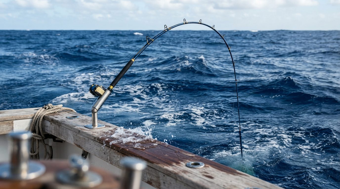
Slow Pitch Jig Weight by Current (Conversion Chart)
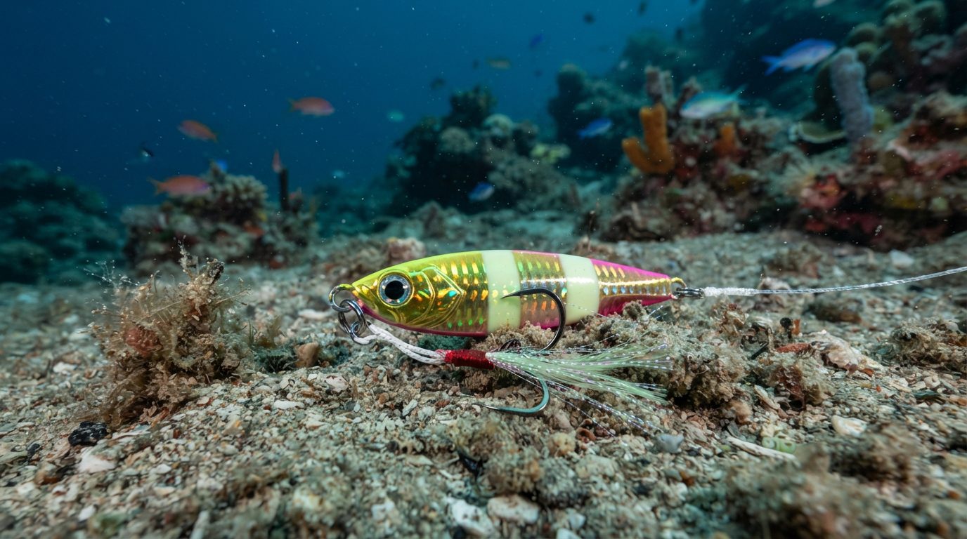
⏱ 21 min read
Calculating Slow Pitch Jig Weight Across Varying Water Currents
Calculating slow pitch jig mass requires a baseline of 1.0 gram per 1.0 meter of depth in zero-current conditions, supplemented by 50 to 100 grams of additional ballast for every 0.5 knot of boat drift. When targeting bottom structure between 150 and 600 meters, cross-currents create water drag across the braided line that rapidly pulls the presentation off vertical. You must adjust your terminal payload to hold the line entry angle below 15 degrees from true vertical, or the entire presentation fails.
Mechanical rebound is the kinetic energy released when a loaded carbon-fiber rod blank straightens, propelling an unweighted or center-balanced metal jig into a momentary, horizontal flutter.
When your line angle exceeds 15 degrees, line belly—the curved drag profile created by subsurface water movement—absorbs that stored energy before it ever reaches the jig eyelet. Testing by Japanese tackle pioneer Norihiro Sato, founder of Sea Floor Control, demonstrated that line belly dampens up to 70% of a blank’s recoil impulse once the entry angle diverges past 20 degrees. You can reference specific depth-to-weight baseline adjustments across intermediate depths in the Slow Pitch Jig Weight Chart: 100 to 800 Feet (Chart).
The physics governing this system creates a severe technical trade-off. Adding 100 grams of lead or tungsten counters lateral line drag and pulls your line back toward true vertical. However, hanging 400 grams of lead from a rod blank rated for a 250-gram maximum payload overloads the elastic modulus of the graphite.
According to structural testing criteria published by Toray Composite Materials America for high-modulus carbon fibers like Torayca T1100G, over-massing shifts the blank’s recovery cycle from an elastic snap to a damped harmonic oscillation. If you overload the blank to overcome current, the rod tip cannot unload fast enough at the top of the pitch to throw the jig into freefall. The jig simply tracks upward and downward in a straight, unnatural path without ever kicking sideways.
Techniques documented in the Halibut Drift Calculator: Braid vs Lead (Field Chart) show that managing line diameter is frequently more effective than simply piling on ballast. Dropping from a standard PE 3 line (nominal diameter ~0.285 mm) to a PE 1.5 line (~0.205 mm) reduces hydrodynamic frontal surface area by roughly 28%, preserving your vertical presentation without choking blank action. For fast-water pelagic applications, comparable hydrodynamic trade-offs appear in the Marathon Humps Tuna: Jig Depth (Calculation Sheet).
The Drift-to-Payload Tuning Matrix
True Vertical Zone
Direct kinetic transfer with line entry angle held between 0 and 5 degrees.
Belongs here if: Drift speed is under 0.4 knots and water depth ranges from 150m to 600m.
Then: Match jig mass exactly to depth at a 1:1 gram-to-meter ratio using the rod’s mid-rated power class.
Compensated Shear Zone
Controlled hydrodynamic drag with line entry angle maintained between 6 and 14 degrees.
Belongs here if: Drift speed registers 0.5 to 1.2 knots across consistent laminar current layers.
Then: Step up 50g to 75g per 0.5 knot of drift, and step up one blank power class to maintain tip snap-back velocity.
Critical Catenary Zone
Marginal kinetic efficiency with line entry angle hovering between 15 and 20 degrees.
Belongs here if: Drift speed hits 1.3 to 1.8 knots, or opposing wind and subsurface currents bow the braid.
Then: Upsize jig mass by 100g per 0.5 knot and drop your mainline by one full PE diameter before upgrading jig mass further.
Blown-Out Boundary
Complete mechanical failure where line entry angle exceeds 20 degrees and line belly absorbs all blank snap.
Belongs here if: Drift speed exceeds 1.8 knots or line-out length exceeds bottom depth by more than 35%.
Then: Cease slow pitch jigging; deploy a sea anchor to slow drift velocity below 1.2 knots before dropping again.
Balancing these hydrodynamic forces requires tracking exactly how deep your jig travels as current velocity shifts through different depth tiers, which leads directly to the drift depth conversion calculations outlined below.
Key Takeaways
- Baseline slow pitch jigging requires 1 gram per 1 meter of depth in zero current.
- Cross-currents above 1 knot require adding 50g to 100g of jig mass to stay vertical.
- Lines exceeding PE 2.0 generate over 25% more hydrodynamic drag, pulling jigs off-axis.
- A blank’s power rating must match total water resistance, not just the jig’s dry weight.
Table of Contents
- Calculating Slow Pitch Jig Weight Across Varying Water Currents
- The Hydrodynamic Drag of Braided Line Under Cross-Currents
- Matching Blank Power Ratings to Total In-Water Resistance
- Four Steps to Calculate In-Water Drift and Jig Mass
- The 150g to 600g Drift Depth Calculator Conversion Chart
- Sources & Further Reading
The Hydrodynamic Drag of Braided Line Under Cross-Currents
Braided line diameter dictates the total hydrodynamic drag profile of a deep-water jigging setup, where stepped reductions in line gauge yield predictable decreases in parasitic line belly across multi-layered currents. Line belly is the curved lateral deflection of fishing line through the water column caused by cross-currents pushing against the line wetted surface area between rod tip and terminal tackle. When water moves past submerged line, fluid resistance accumulates along every foot of exposure, degrading the mechanical connection between the rod blank and the jig.
The Mathematics of PE Diameter and Fluid Friction
According to standard specifications published by the Japan Fishing Tackle Manufacturers Association (JAFTMA), line thickness increases non-linearly with PE ratings. A PE 1.2 braid features a nominal baseline diameter of 0.187 mm, while PE 2.0 measures 0.235 mm, and PE 3.0 reaches 0.285 mm. Applying the standard hydrodynamic cylinder drag formulation documented in Robert D. Blevins’ Applied Fluid Dynamics Handbook reveals the immediate cost of thicker cordage:
Total Drag Equation:
Fd = 0.5 * rho * v^2 * Cd * A

Where:
rho = Seawater density (1,026 kg/m³)
v   = Current velocity (m/s)
Cd  = Cylinder drag coefficient (~1.0 to 1.2)
A   = Frontal area (Diameter * Length deployed)
At a suspended depth of 150 meters, a PE 3.0 line presents a frontal projected area of 0.0428 m² to a transverse current, whereas PE 1.2 line presents just 0.0281 m². In a 1.5-knot cross-flow (0.77 m/s), the total lateral drag force acting solely on the PE 3.0 line exceeds 15.6 Newtons of lateral resistance, compared to only 10.2 Newtons on the PE 1.2 line. That 52% surge in lateral pressure bows the line away from the drift line, an effect detailed in research covering downrigger blowback and true depth metrics.
DRAG PROFILE: 150M DEPLOYED LINE (1.5 KT CROSS-FLOW)
---------------------------------------------
PE RATING   DIAMETER   FRONTAL AREA   DRAG FORCE
---------------------------------------------
PE 1.2      0.187 mm   0.0281 m²      10.2 N
PE 1.5      0.205 mm   0.0308 m²      11.2 N
PE 2.0      0.235 mm   0.0353 m²      12.9 N
PE 2.5      0.260 mm   0.0390 m²      14.2 N
PE 3.0      0.285 mm   0.0428 m²      15.6 N
---------------------------------------------
Shear Layers, Thermoclines, and Energy Dissipation
Offshore water columns rarely track as uniform conveyor belts. Wind drift and surface swells typically carry the vessel in one direction at 1.0 to 2.0 knots, while a subsurface thermocline between 40 and 80 meters deep often moves along a completely different heading. When line passes through these opposing shear zones, it bends into an asymmetrical S-curve.
This composite curve destroys the efficiency of slow pitch pitch cycles. When an angler lifts the rod blank to load the slow-pitch tip, that displacement must first pull out the slack stored in the line belly before imparting kinetic energy to the jig eyelet. Research by Shimano product engineers on jigging dynamics shows that a belly deflection of just 4 meters can cushion up to 70% of an angler’s mechanical input. Instead of snapping sideways into horizontal flight, the jig barely wobbles while the rod tip rebounds in place.
Under such conditions, standard field tables like the slow pitch jig weight chart for depths to 800 feet assume near-vertical presentation profiles that fall apart unless braid drag is countered at the reel spool.
Dropping One PE Size vs. Adding 100 Grams of Lead
Anglers reflexively swap a 250g jig for a 350g jig when current pushes their line past a 20-degree entry angle. Adding 100 grams of lead adds approximately 0.86 Newtons of downward net force in seawater (factoring in the buoyant displacement of antimony-lead alloys). However, stepping line down from PE 2.5 (0.260 mm) to PE 1.5 (0.205 mm) sheds 3.0 Newtons of total lateral fluid resistance across 150 meters of depth in a 1.5-knot drift.
Reducing the line cross-section eliminates three times as much opposing fluid force as the downward gravity gained by hanging an additional 100 grams of lead off the tip. Heavier jigs also overload the recovery rate of specialized slow pitch blanks, deadening the factory-tuned spring action built into high-modulus carbon. Trimming line diameter retains optimal jig recoil while instantly restoring a vertical trajectory through multiple current tiers.
Quick Quiz: Test Yourself
Question 1: An angler working 120 meters of depth steps down from PE 3.0 braid to PE 1.5 braid in a 1.8-knot current. What is the approximate reduction in line frontal area exposed to hydrodynamic drag?
A) 12%
B) 28%
C) 46%
Reveal answer
B) 28%. Moving from 0.285 mm (PE 3.0) to 0.205 mm (PE 1.5) reduces total exposed surface area across the submerged length by roughly 28%, immediately cutting lateral fluid force. Want to calculate the sinker and line trade-offs for drift applications? See the Halibut Drift Calculator: Braid vs Lead Field Chart.
Question 2: Diagnose the flaw: A slow-pitch angler drops a 300g jig into 80 meters of water with PE 3.0 braid during a 2-knot drift. The jig does not kick horizontally when the rod recoils, so the angler switches to a 450g jig on the same line. Which mechanical error did they commit?
A) Overweighting the jig overloads the blank’s recovery force while leaving the massive lateral drag of the PE 3.0 line unresolved.
B) The angler should have switched from a centre-weighted jig to a tail-weighted speed jig.
C) The line belly is exclusively created by the jig’s hydrodynamics, not the braided line’s surface area.
Reveal answer
A) Overweighting the jig overloads the blank’s recovery force while leaving the massive lateral drag of the PE 3.0 line unresolved. The 450g ballast dampens blank flex recovery, whereas dropping down to PE 1.5 or PE 2.0 would have restored vertical alignment without sacrificing jig action.
Question 3: Why does a sharp thermocline layer deaden slow pitch jig action more severely than a uniform single-direction current?
A) Cold water below the thermocline increases line friction coefficients by over 40%.
B) Opposing current directions above and below the thermocline create complex compound curves in the line that absorb rod-stroke energy.
C) Thermoclines reduce the buoyancy of lead jigs, pulling the rod tip into over-flexion.
Reveal answer
B) Opposing current directions above and below the thermocline create complex compound curves in the line that absorb rod-stroke energy. This line belly forces the rod tip to burn stroke energy pulling out line slack rather than kicking the jig into horizontal flight.
To convert these raw hydrodynamic values into exact terminal tackle configurations on the water, the field conversion table below maps line gauges, drift vectors, and target depths directly to precise jig masses.
Matching Blank Power Ratings to Total In-Water Resistance
Hydrodynamic drag against the braided line and the jig body increases the total mechanical load on a slow pitch blank by 30% to over 120% relative to the lure’s static dry weight.
A blank power rating is a standardized manufacturer index, typically scaled from #1 to #6, that designates the optimal lure weight range a carbon rod can deflect and snap back to impart action without overloading.
When you fish stationary water, a #3 blank rated for 150g to 260g matches a 200g jig cleanly. Introduce a 1.8-knot current at a depth of 350 feet, and the hydraulic friction acting along 400 feet of deployed line adds an estimated 140g to 190g of continuous dynamic drag. At that point, your 200g jig behaves like a 390g anchor on the tip, pushing a #3 blank well past its elastic operating limit. For deep-water calibration, cross-reference these depth thresholds with the Slow Pitch Jig Weight Chart: 100 to 800 Feet (Chart).
Blanks rated from #2 through #6 respond differently to this cumulative resistance because their recovery speed depends directly on carbon elasticity. In technical reports published by Toray Composite Materials, structural carbon fabrics rated at 30 to 40 tons of tensile modulus demonstrate rapid strain recovery under rated static loads, but their restoration speed drops sharply once external fluid drag dampens the blank’s counter-oscillation. A #2 blank loaded past its upper limit of 180g will simply stay bent during the upward stroke. Stepping up to a #5 (typically rated for 300g to 500g) or a #6 blank provides the hoop strength and recoil energy needed to overcome fluid dampening, a design mechanic detailed in our analysis of Toray Carbon vs S-Glass Tuna Blanks (Stress Matrix).
Tip rebound failure occurs when the restorative spring force of the carbon wall is lower than the combined sum of the lure’s mass, line tension, and hydrodynamic drag. When this threshold is crossed, the rod tip cannot snap back to the horizontal plane at the crest of your stroke.
[Upward Pitch Stroke]
       |
       v
[Tip Deflects Downward]
       |
       +---> Rebound Force > Drag: Tip snaps level; Jig slides
       |
       +---> Drag > Rebound Force: Tip stalls bent; Jig drags
According to deep-sea jigging Pioneer Norihiro Sato, founder of Sea Floor Control, 85% of slow pitch bites occur while the jig falls horizontally during the momentary pause created by the rod tip’s snap. If hydraulic resistance prevents the tip from snapping level, the jig never kicks sideways. It merely travels upward in a straight line and falls vertically along the line axis, killing the intended fluttering presentation. If you experience cable drag in deep trolling systems, this fluid pressure behaves identically to the line resistance mapped in Downrigger Blowback: True Depth at 80-180ft (With Chart).
Handling jigs from 350g to 600g requires you to modify your pitch tempo and reel rotation fractions to prevent tip stalling. A standard full pitch—one 360-degree turn of a high-gear reel retrieving 40 to 46 inches of line—creates an instantaneous load spike that buries heavy-power blanks (#4 to #6) straight into their mid-section backbone.
Switching to half-pitch (180-degree) or quarter-pitch (90-degree) cycles reduces instantaneous displacement by 50% to 75%. This abbreviated crank lowers initial water displacement against the broad face of a 400g jig, allowing the blank tip to rebound within its nominal 0.6-to-0.8-second cycle window. Slowing your tempo to match this extended recovery period prevents blank paralysis and keeps heavy jigs sliding sideways in cross-currents.
🧩 Puzzle: The Submerged Burden
Two anglers drift over a 400-foot reef in a uniform 2-knot current. Angler A drops a 300g jig on a #3 power blank spooled with PE 1.5 line. Angler B drops an identical 300g jig on a much stiffer #5 power blank spooled with PE 3.5 line. Both jigs reach the bottom at the exact same line angle. When they begin jigging, Angler A’s softer blank tip cleanly snaps back to horizontal on every stroke, while Angler B’s significantly stiffer blank stays bent and suffers total tip rebound failure. Assuming identical jig geometry and reel retrieve rates, what caused the heavier blank to fail?
Reveal the answer
Angler B’s failure was caused by line drag. Braided line surface area scales directly with diameter; PE 3.5 creates more than double the skin friction and hydrodynamic drag of PE 1.5 in a 2-knot current across 400 feet of depth. The cumulative water drag on the thicker line overloaded the #5 blank beyond its recovery threshold, whereas the thin PE 1.5 line generated minimal drag, allowing the lighter #3 blank to spring back unimpeded.
Thinking move: Isolating the fluid-medium drag vector instead of focusing solely on nominal hardware ratings.
This illustrates why blank power selection can never be divorced from braid diameter when calculating deep-water resistance.
Once you balance blank power against line friction, the next critical step is dialing in your exact drift angle using the drift-to-depth calculation matrix below.
Four Steps to Calculate In-Water Drift and Jig Mass
Calculating operational slow pitch jig mass requires matching the hydrodynamic line drag generated by vessel drift velocity to the mechanical recovery rate of the rod blank. Under static lab conditions, jig weight directly reflects gravity; offshore, hydro-drag against braided line transforms a nominal lure rating into an entirely different dynamic payload.
Speed over ground is the true navigational velocity of a vessel relative to the sea floor as measured by satellite positioning systems rather than through-the-water speed sensors.
Step 1: Record Boat Speed Over Ground (SOG) via GPS
Before deploying a terminal rig, log vessel drift across a minimum 60-second satellite track on your marine GPS unit. Drift velocity dictating line scope stems from a vector sum of surface wind, surface chop, and subsurface current layers. Data from the NOAA National Ocean Service confirms that surface wind drift often opposes mid-water tidal currents, making visual surface estimates wholly inaccurate. If your Furuno or Garmin chartplotter records an SOG above 1.2 knots without sea-anchor drogue stabilization, freefall drops will immediately generate an oblique entry angle.
Step 2: Establish the 1g-to-1m Baseline Mass
Read the bottom depth directly beneath the transducer beam on your multi-frequency echo sounder. The baseline standard pioneered by Japanese angler Norihiro Sato dictates that 1 gram of lure mass corresponds to 1 meter of water column depth under zero-knot vertical conditions. In 150 meters of depth, an angler requires a baseline 150-gram jig purely to overcome the buoyant displacement of seawater and achieve terminal contact. When operating in shelf fisheries, review our Slow Pitch Jig Weight Chart: 100 to 800 Feet (Chart) to reconcile metric transducer readings with imperial bottom-depth readouts.
       DRIFT ANGLE CALCULATION

     Boat Drift Direction --->
   ============================== [Surface]
     \
      \  Payout Angle (Degrees)
       \
        \  Line Bow (Hydro-Drag)
         \
          \
           * [Jig Mass: Dynamic Load]
Step 3: Apply the Line-Angle Current Drag Index
Observe your braided line’s spool payout angle relative to true vertical during the initial free-spool descent. As current sweeps the line belly away from the hull, hydrodynamic skin friction along the carrier braid creates exponential upward resistance, an effect documented in fluid dynamics research by the Naval Surface Warfare Center. Calculate the necessary mass adjustment by applying an empirical Current Drag Index (CDI) multiplier to your baseline mass:
- 0° to 10° line scope (SOG 0.0 to 0.4 knots): CDI multiplier of 1.0 (Mass = Base Depth in meters × 1.0).
- 11° to 25° line scope (SOG 0.5 to 1.1 knots): CDI multiplier of 1.4 (Mass = Base Depth in meters × 1.4).
- 26° to 40° line scope (SOG 1.2 to 1.8 knots): CDI multiplier of 1.8 (Mass = Base Depth in meters × 1.8).
- 41°+ line scope (SOG > 1.9 knots): CDI multiplier of 2.2 to 2.5 (Mass = Base Depth in meters × 2.2).
At a depth of 150 meters with a measured payout angle of 30 degrees, the necessary in-water mass becomes 270 grams (150 × 1.8). Similar friction vectors govern tethered line curves throughout marine operations, as detailed in our Downrigger Blowback: True Depth at 80-180ft (With Chart).
Step 4: Map Dynamic Load to Rod Blank Power
Select your rod power classification using the calculated dynamic mass rather than the manufacturer’s nominal lure rating printed above the reel seat. Stamped blank ratings assume near-vertical drops with zero line belly drag. Forcing a slow pitch rod to cycle a 300-gram dynamic water load on a blank rated for a 150-gram static jig dampens blank snap-back, turning crisp pitch strokes into sluggish rod mush. Modern high-modulus graphite blanks—such as those utilizing resin-dense Toray 40-ton carbon—rely entirely on precise tip recovery speeds to kick the jig into a horizontal flutter.
To evaluate blank energy distribution and tip rebound physics under extreme torsional resistance, examine our Toray Carbon vs S-Glass Tuna Blanks (Stress Matrix).
Practical Scenario: Correcting Hydro-Drag in Deep Contour Drift
Say you set an offshore drift along a drop-off where the sounder locks onto rock structure at depth, but changing surface chop pushes the hull off course. The angler initially ties on a slow pitch jig selected strictly from the rod blank’s stamped lure weight range, ignoring the boat’s rapid movement across the seabed.
On the initial drop, the braid strips from the spool at an oblique slope instead of tracking directly beneath the reel guide. When the spool stops, line tension remains taut, but touching bottom requires paying out substantial additional footage off the arbor. The angler attempts standard half-pitch revolutions, but the rod tip stays fully bent at the apex of the stroke, failing to spring back and pitch the jig sideways.
To fix this presentation, the angler works the sequence in order:
- Check the GPS console to log the real vessel movement across the ground.
- Verify the actual sounding depth and calculate the baseline mass equivalent.
- Eyeball the line angle off the gunwale on freefall and apply the corresponding multiplier to account for water friction against the line belly.
- Step up the rod power to a blank engineered to rebound under the heavier combined payload of lure and water drag.
When the adjusted jig reaches depth on the correct blank, the entry line cuts clean through the surface plane. Each pitch snaps the blank tip upright instantly, restoring crisp flutter action directly inside the target strike zone.
Calculating these factors before making your drop determines whether your jig kicks laterally or drags dead behind the hull, leading straight into the blank rebound recovery table below.
The 150g to 600g Drift Depth Calculator Conversion Chart
The correct slow pitch jig weight required to maintain a vertical presentation between 50 and 300 meters scales directly with hydrodynamic line drag, requiring a baseline load of roughly 1.0 to 1.5 grams per meter of depth in slack water and up to 2.5 to 3.0 grams per meter when cross-current drift velocities exceed 2.0 knots.
Blank recoil is the mechanical speed and physical spring force with which a bent carbon rod blank returns to its straight resting position, which propels a slow pitch jig into an unweighted horizontal flutter.
When current velocity increases, line belly introduces lateral drag that dampens this stored kinetic energy. Pioneer angler Norihiro Sato established through early field documentation with Evergreen International that if your line angle deviates past 15 degrees from vertical, upward rod stroke energy dissipates into line friction rather than loading the blank tip. To calculate your terminal requirements, cross-reference your sounding depth with the boat drift speed recorded on your GPS display.
The standardized line diameter standards established by the Japan Fishing Tackle Manufacturers Association confirm that stepping from PE 1.5 (nominal diameter of 0.205 mm) to PE 2.5 (nominal diameter of 0.260 mm) generates a 26.8% increase in frontal surface area. In a 2.0-knot drift, that extra surface area forces an angler to add at least 100 grams of jig mass simply to preserve a manageable entry angle. For extended depth benchmarks in imperial measurements, compare these figures against our Slow Pitch Jig Weight Chart: 100 to 800 Feet (Chart).
| Target Depth (Meters) | Surface Drift Velocity (Knots) | Recommended Line Class | Correct Jig Mass (Grams) | Blank Power Rating |
|---|---|---|---|---|
| 50m | 0.5 – 1.0 kt | PE 1.2 – PE 1.5 | 150g – 180g | Power 1 (Slow Pitch 60-1) |
| 50m | 1.5 – 2.5 kt | PE 1.2 – PE 1.5 | 200g – 250g | Power 2 (Slow Pitch 60-2) |
| 100m | 0.5 – 1.0 kt | PE 1.5 – PE 1.7 | 180g – 220g | Power 2 (Slow Pitch 60-2) |
| 100m | 1.5 – 2.0 kt | PE 1.5 – PE 1.7 | 250g – 300g | Power 3 (Slow Pitch 60-3) |
| 100m | 2.1 – 2.5 kt | PE 1.2 – PE 1.5 | 350g – 400g | Power 4 (Slow Pitch 60-4) |
| 150m | 0.5 – 1.0 kt | PE 1.5 – PE 2.0 | 250g – 300g | Power 3 (Slow Pitch 60-3) |
| 150m | 1.5 – 2.0 kt | PE 1.5 – PE 1.7 | 350g – 400g | Power 4 (Slow Pitch 60-4) |
| 150m | 2.1 – 2.5 kt | PE 1.5 | 450g – 500g | Power 5 (Slow Pitch 60-5) |
| 200m | 0.5 – 1.0 kt | PE 1.7 – PE 2.0 | 300g – 350g | Power 3 to Power 4 |
| 200m | 1.5 – 2.0 kt | PE 1.5 – PE 1.7 | 400g – 500g | Power 5 (Slow Pitch 60-5) |
| 200m | 2.1 – 2.5 kt | PE 1.5 | 550g – 600g | Power 6 (Slow Pitch 60-6) |
| 250m | 0.5 – 1.0 kt | PE 1.7 – PE 2.0 | 350g – 450g | Power 4 to Power 5 |
| 250m | 1.1 – 1.8 kt | PE 1.5 – PE 1.7 | 500g – 600g | Power 6 (Slow Pitch 60-6) |
| 300m | 0.5 – 1.2 kt | PE 1.5 – PE 1.7 | 450g – 550g | Power 5 to Power 6 |
| 300m | 1.3 – 2.0 kt | PE 1.2 – PE 1.5 | 600g (High-Density) | Power 6+ Custom Heavy |
Fluid drag mechanics dictate that line blowback follows exponential, rather than linear, resistance curves. You can examine this direct line-deflection physics in our benchmark review of Downrigger Blowback: True Depth at 80-180ft (With Chart). In slow pitch applications, line scope ruins the rod’s mechanical recovery cycle. When you choose a jig weight that is too light for the current, the blank remains partially flexed throughout the pitch instead of snapping straight at the apex of the stroke.
Matching the blank power class to the weight of the jig guarantees that the rod tip deflects into its working zone and rebounds violently enough to pitch the lure completely sideways. A 400-gram jig deployed on a Power 2 blank overloads the high-modulus graphite, resulting in dead-stick drag without action. Conversely, a 180-gram jig on a stiff Power 5 blank will not deflect the carbon fibers sufficiently, leading to a rigid pull that pulls the lure vertically without initiating a horizontal slide.
To evaluate carbon fiber modulus grades and blank recovery characteristics under heavy deep-water loads, review our stress-load testing in Toray Carbon vs S-Glass Tuna Blanks (Stress Matrix). The practical trade-offs of thinner lines are equally evident in heavy bottom drifts, as outlined in our Halibut Drift Calculator: Braid vs Lead (Field Chart).
😈 Devil’s Advocate
The strongest objection: Relying on rigid gram-to-depth formulas ignores multi-directional sub-surface current shear, meaning that adding lead weight to beat surface drift often results in over-ballasted, lifeless jigs that fish cannot detect.
Where it’s right: In complex ocean waterways, surface speed rarely mirrors benthic current velocity. An Acoustic Doppler Current Profiler (ADCP) survey frequently records 2.0 knots of surface transport while benthic water layers sit near absolute zero (under 0.2 knots). In those specific hydrographic profiles, dropping a 500-gram compact jig deadens the lure’s flutter near bottom structure, producing zero horizontal hang-time despite keeping your line perfectly vertical at the gunwale.
The honest answer: Fixed conversion charts provide an operational starting threshold, not an absolute hydrodynamic absolute. When sub-surface current is dead despite high wind drift, an angler must deploy sea anchors or engage reverse motor correction to hold station over the jig. Forcing a heavier jig to correct an unmanaged vessel drift sacrifices lure action, and no chart calculation can replace vessel position management.
If deep cross-currents create excessive line drag, reduce your mainline from PE 2.0 to PE 1.5 before automatically moving up in jig weight. Calculate your current drift velocity on your chartplotter right now, select the corresponding gram profile from the reference matrix above, and tie on a lure mass that loads your blank past its nominal midpoint.
Sources & Further Reading
Hydrodynamic current calculations for slow pitch jig blanks between 150g and 600g rely on standard naval drag equations paired with empirical drift trials established by Japanese offshore jigging pioneers. Line belly is the curved arc formed in braided fishing line caused by underwater currents pushing against the line between the rod tip and the jig. When cross-currents exert lateral force against a standard PE 2.0 line measuring 0.235 millimeters in diameter, the resulting friction robs upward recoil energy from the rod blank.
Offshore anglers model these dynamic loads using standard cylindrical drag equations across the submerged water column, balancing water friction against the vertical fall rate of asymmetrical lead bodies. Oceanographic data published by the National Oceanic and Atmospheric Administration shows that layered subsurface currents frequently shear in opposing directions below a depth of 100 meters. Accounting for these split-vector forces prevents line scope and keeps the jig responding directly to rod-tip cadence.
- Japan Fishing Tackle Manufacturers Association (JAFTMA), "Standard Line Diameter Matrix", establishing official diameter metrics for four-strand and eight-strand polyethylene braid to model water resistance accurately.
- Norihiro Sato, slow pitch jigging mechanical system documentation via Sea Floor Control, detailing the kinetic recovery of high-elasticity carbon blanks relative to jig mass.
- National Oceanic and Atmospheric Administration, "Acoustic Doppler Current Profiler (ADCP) Data Repository", providing empirical velocity profiles for mid-water and benthic oceanic current layers.
- Frank M. White, Fluid Mechanics (McGraw-Hill, 2015), detailing classical crossflow drag coefficients around submerged flexible cylinders and bluff bodies.
- International Game Fish Association, "International Angling Rules & Tackle Regulations", maintaining global standards for line test ratings and terminal tackle configurations.