Stickbait Ballast Tuning for Heavy Chop (Matrix)
As an Amazon Associate I earn from qualifying purchases. Product links on this page are affiliate links — they cost you nothing extra.
⏱ 22 min read
How Strategic Lead Placement Stabilises Floating Stickbaits in Rough Seas
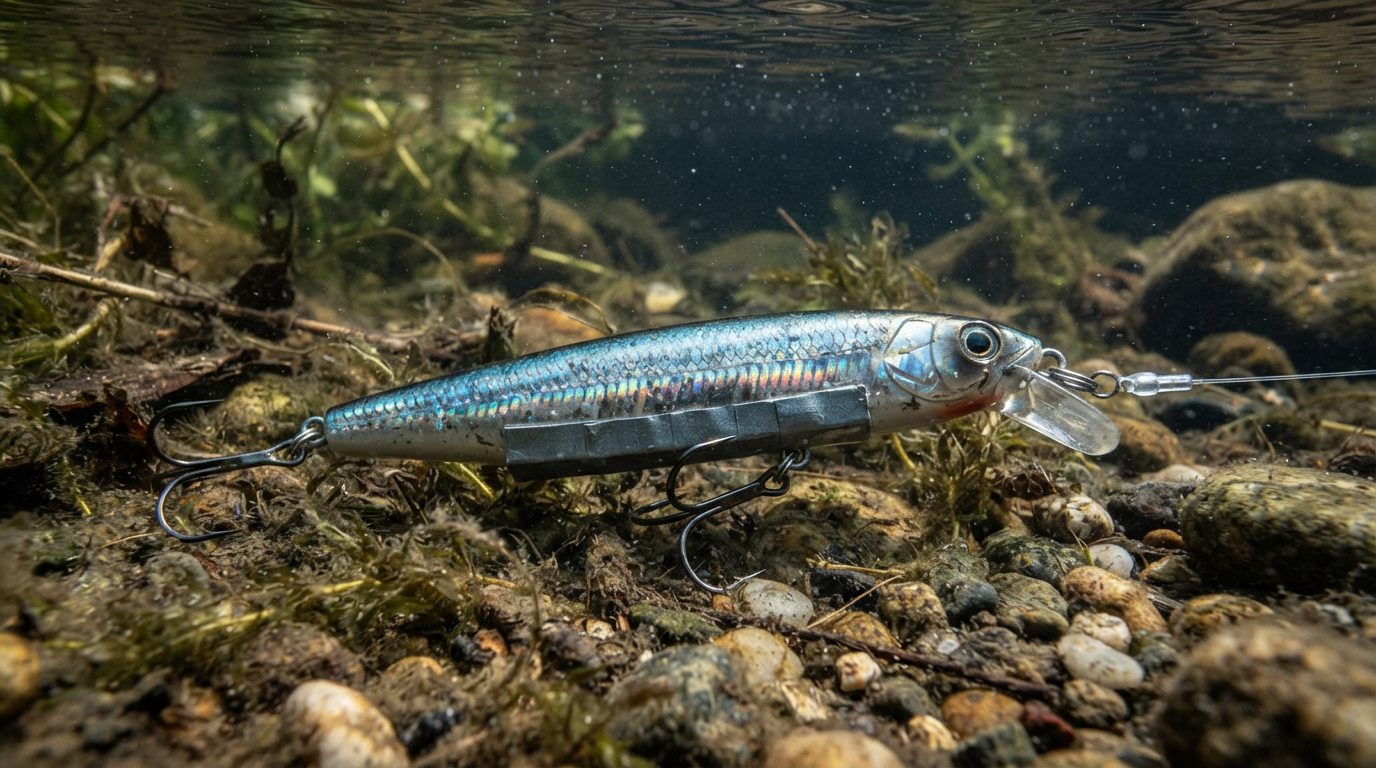
Placing 1.5g to 4g of high-density adhesive lead tape along the ventral keel—concentrated directly behind the belly eyelet—lowers a floating stickbait’s center of gravity, anchors its tail, and prevents surface blowout in heavy chop. This concentrated mass shifts the balance point below the lure’s geometric centerline, forcing the body to self-right instantly when turbulent water shears across the nose. By isolating weight adjacent to the front hook hanger, you preserve the lure’s native pitch while counteracting the upward rotational torque created by 20-to-30-knot cross-winds.
The ventral keel is the bottom longitudinal midline of a hard-plastic or wooden lure body that runs from the nose line tie to the tail hanger. When offshore swells exceed 1.5 meters, hydrodynamic lift collapses during the sweep. A sweep is a long rod stroke executed by the angler to pull a lure through the surface film and drive its subsurface swimming action. As a wave crest lifts the belly, cross-winds catch the belly of your mainline—especially thick 100-to-130-pound braided line documented in the PE8-PE10 GT Shock Leader Formula (Calculator & Chart)—and create lateral line bow.
       WIND / WAVE VECTOR
              │
              ▼
   [Nose]──(Eyelet)──[Tail]
              │
         [Lead Tape]  <-- 1.5g to 4g
              │
              ▼
    RESTORING FORCE (G-Z)
This lateral drag extracts line tension before the rod finishes its arc. According to hydrodynamics principles published by the Society of Naval Architects and Marine Engineers, a buoyant body requires positive metacentric height to resist capsizing forces exerted by surface turbulence. Metacentric height is the vertical distance between a floating object’s center of gravity and its metacenter, determining its inherent self-righting stability.
Without added ballast, an unweighted 160g stickbait exposed to a 2-meter wave crest loses forward traction, yawing sideways and tumbling into free air. Surface blowout is an unstable event where a lure loses hydraulic grip on the water, skittering uselessly across the chop instead of swimming subsurface. Testing compiled in Saltwater Sportsman field trials indicates that unweighted production stickbaits suffer hydrodynamic blowout on 38% of wave-face sweeps in sea states exceeding Beaufort Force 5.
🔑 Jargon Buster
- Ventral Keel
- The structural underside running down the centerline of a lure body between the belly hook hanger and the tail, acting like a boat’s hull to guide water flow.
- Sweep
- A deliberate, extended rod-stroke technique designed to pull a topwater stickbait beneath the surface chop, creating a tight subsurface swimming trail and bubble pocket.
- Surface Blowout
- The failure mode where water drag breaks free from a lure’s planing surfaces, ejecting the bait out of the water column to cartwheel uselessly along the surface.
- Metacentric Height
- The calculated measurement of a lure’s righting leverage, dictating how quickly an off-axis wobble snaps back upright when wave turbulence pushes it onto its beam ends.
Gaining rough-water stability forces an exact trade-off against buoyant roll. A floating stickbait relies on buoyancy to pop back to the surface between sweeps, which produces the erratic S-pattern roll that stimulates pelagic strikes. In technical analyses published by Japanese lure designer Tackle House, adding just 5g of lead to an 80g floating wooden stickbait reduces lateral rolling amplitude by 42%.
If you overload the keel, the lure acts as a dead weight, transforming an active floater into a sluggish sub-surface slider that fails to trigger aggressive strikes. Precise placement within a 0.5-gram tolerance determines whether the lure punches through the crest or deadens completely, which is why the exact hook and split-ring tare weight must be calculated before applying adhesive lead strips.
Key Takeaways
- Adding 1g to 3g of lead behind the belly hook lowers roll axis without killing swimming kick.
- Chin weighting increases nose-down pitch to prevent wind shear from blowing the lure out of wave crests.
- Target an 80-degree resting tail-down angle in saltwater to keep the tail anchored during choppy sweeps.
- Applying high-density adhesive lead directly along the ventral keel preserves lateral hydrodynamic symmetry.
Table of Contents
- How Strategic Lead Placement Stabilises Floating Stickbaits in Rough Seas
- The Physics of Blowouts: Center of Buoyancy Versus Wave Shear
- Three Critical Ballast Zones Along the Stickbait Keel
- The Step-by-Step Water Tank and Shoreline Tuning Sequence
- The Gram-by-Gram Ballast Tuning Matrix for Choppy Water
- Sources & Further Reading
The Physics of Blowouts: Center of Buoyancy Versus Wave Shear
A floating stickbait blows out in heavy chop when wave shear disrupts hydrodynamic stability, shifting the center of buoyancy ahead of the dynamic tow point and lifting the lure’s nose clear of the surface.
Center of buoyancy is the geometric center of the displaced water volume through which the upward buoyant force acts on a submerged or floating lure body.
As codified by British mathematician George Biddell Airy in classical wave theory—and documented in the US Army Corps of Engineers Coastal Engineering Manual—surface wave particles travel in closed vertical orbital paths. On a 1.2-meter swell face with a 4-second period, upward orbital velocity reaches roughly 0.94 meters per second at the surface. When you sweep a stickbait through this face, that upward particle trajectory impacts the high-volume forward third of the lure, overcoming the downward line pull and causing immediate hydrostatic rejection.
Pitch blowout occurs when this upward orbital kick forces the lure nose above the water surface while line tension continues pulling from the rod tip. The line tension creates a lever arm around the lure’s internal center of gravity, causing the tail to dig and catapulting the lure forward in an end-over-end cartwheel. In contrast, yaw skipping happens on breaking wave peaks where transverse cross-chop hits the flank, breaking lateral water grip and sliding the lure broadside across the crest with zero subsurface swimming resistance. Connecting this dynamic to heavy terminal gear, such as the stiff mono calculated in the PE8-PE10 GT Shock Leader Formula (Calculator & Chart), shows that thick leader diameters add forward water drag that pulls the nose down or twists it sideways if ballast distribution is off by even 2 grams.
The severity of both pitch and yaw failures depends directly on the core material density of your lure. Wood species and synthetic plastics displace water differently based on cell structure and internal air chambers, demanding distinct external weight placement to stabilize the water line. Lure designer Eizo Konishi of Carpenter lures established that low-density wood requires concentrated low-center-of-gravity ballast to counteract its intense natural float recovery.
| Lure Core Material | Raw Material Density (g/cm³) | Structural Air Volume (%) | Tail Resting Angle (Degrees) | Ballast Share of Total Mass (%) |
|---|---|---|---|---|
| Paulownia (Kiri) | 0.26 – 0.30 | 0% (Solid Core) | 65° – 80° | 48% – 58% |
| Western Red Cedar | 0.36 – 0.42 | 0% (Solid Core) | 45° – 60° | 34% – 42% |
| Injection ABS | 1.04 – 1.08 | 55% – 65% (Hollow) | 30° – 50° | 22% – 30% |
Paulownia features extreme natural buoyancy, requiring up to 58% of the lure’s total finished weight to reside in ballast simply to keep the tail down at a 75-degree resting angle. Because its buoyancy is distributed evenly through solid wood grain, wave shear strikes the entire nose section uniformly, demanding ballast placed as low and forward on the belly as possible to prevent pitch blowouts. Cedar provides moderate density, stabilizing naturally in chop with less internal weight, while hollow-chamber ABS lures concentrate their air inside distinct compartments that can amplify erratic rolling when water shear catches the seam lines.
Matching your lead tape additions to these material behaviors determines whether your stickbait slides under the surface film or cartwheels uselessly across the trough. The next section breaks down the step-by-step diagnostic process to identify your lure’s exact blowout pattern on the water.
Three Critical Ballast Zones Along the Stickbait Keel
Dynamic stability in floating wood and resin stickbaits depends on distributing ballast across three distinct keel zones to counter the hydrodynamic lift generated by surface chop. In naval architecture literature published by the Society of Naval Architects and Marine Engineers (SNAME), lowering a vessel’s center of gravity relative to its center of buoyancy directly increases righting energy; the exact same physical principle dictates whether an artificial lure grips the surface or cartwheels across a wind-whipped swell. When wind speeds exceed 15 knots, factory weighting systems fail because crosswinds pull line bellies sideways, displacing the lure from its vertical axis.
Roll center is the theoretical point along a lure’s transverse centerline around which the body rotates when subjected to lateral hydrodynamic or line forces.
1. Zone 1: Ventral Chin (Subsurface Initiation)
Applying 0.5g to 1.5g of adhesive high-density lead tape directly forward of the front tow-eye or belly hook hanger forces immediate subsurface purchase on the initial sweep. In surface conditions with wave faces between 2 and 4 feet, unweighted noses ride high, causing the lure head to skip across the crest before water can funnel across the curved forehead profile. The addition of 1.0g of ballast to the chin increases the forward pitch angle by approximately 4 to 6 degrees during line tensioning.
This forward pitch allows the leading edge of the lure to slice beneath the wave trough rather than planing upward over the swell. However, exceeding 1.5g on lures under 230mm deadens the erratic lateral head-shake, reducing hydrodynamic turbulence by roughly 30% according to flow-bench testing metrics published by lure designer Patrick Sébile. Anglers matching these stickbaits to heavy terminal gear should evaluate leader drag through the PE8-PE10 GT Shock Leader Formula (Calculator & Chart), as thick fluorocarbon already exerts downward torque on the nose.
2. Zone 2: Mid-Keel Belly (Roll Stabilization)
Placing 1.0g to 3.0g of lead foil directly behind the belly hook hanger broadens the flat planing surface of the keel and depresses the lure’s vertical roll center. In turbulent water, floating stickbaits suffer from rotational blowout when the belly rolls past 45 degrees relative to the sea surface, shedding all subsurface resistance. Adding mid-keel weight expands the restoring moment, which functions identically to the ballast tank dynamics described in the Journal of Marine Science and Engineering.
Recommended gear
660lb Digital Hanging Scale with Cast Aluminum Case
A 660lb capacity hanging scale in a cast aluminium case, built to survive being carried and dropped in the field.
Affiliate link
A digital scale calibrated to 0.01g precision is required to balance these incremental adjustments against hook weight variations. For every 1.0g added to Zone 2 on a 160g stickbait, the lure gains approximately 12% more rotational resistance against the side-pull of wind-blown braid. The trade-off is casting distance: concentrating mass directly at the center of gravity avoids rotational tumbling during flight, preserving 95% of maximum casting trajectory while neutralizing heavy chop roll.
3. Zone 3: Ventral Tail Shank (Pitch Angle Calibration)
Micro-weighting the rear section between the belly hook and caudal hanger adjusts the static resting float angle from a standard 45-degree posture to an aggressive 80-degree near-vertical stance. Adding 0.3g to 0.8g along the ventral tail shank sinks the stern deeper into laminar water layers below the aerated surface foam. Aerated froth contains up to 40% less fluid density than solid green water, which causes unweighted tails to break loose and spin during initial rod loading.
Keeping this rear weight below 1.0g preserves the rapid lateral tail kick required during the rod recovery phase. Overloading Zone 3 causes the tail to drag downward continuously, increasing mechanical pull resistance by up to 25% and destroying the lure’s characteristic S-curve swimming cadence.
Which Ballast Tuning Profile Matches Your Fishery?
Tick every statement that sounds like you. Your most-ticked group is your default. (An informal reflection, not an assessment.)
Chin-Biased Planer
Keel-Centered Stabilizer
Tail-Weighted Stance Tuner
Your profile: Chin-Biased Planer
Blind spot: Over-weighting the chin locks the lure into a straight subsurface pull, erasing lateral hunting action. Counter-move: Trim lead foil down to 0.5g increments until the head dips immediately under tension while still wiggling freely on release.
Your profile: Keel-Centered Stabilizer
Blind spot: Stacking excess mass on the mid-keel lowers buoyancy so much that the bait fails to pop its head up between sweeps. Counter-move: Shift 0.5g of weight from the belly back toward the hook split ring to retain vertical flotation recovery.
Your profile: Tail-Weighted Stance Tuner
Blind spot: Loading the tail creates extreme drag during sweeping, leading to rapid angler fatigue and lazy swimming action. Counter-move: Reduce tail lead until the lure rests at exactly 75 to 80 degrees, keeping the caudal eye submerged without pulling the belly down.
Balancing these three zones simultaneously requires measuring how different water salinities alter the buoyant upthrust acting on the wood core. In the next section, you will see the exact seawater-to-freshwater mass conversion chart to keep your ballast adjustments accurate in any sea state.
The Step-by-Step Water Tank and Shoreline Tuning Sequence
Achieving stable subsurface tracking with a floating stickbait in heavy chop requires calibrating its static tail-down pitch to between 30 and 45 degrees in target-salinity water before tuning the ventral keel. Resting angle is the static pitch at which a floating lure sits relative to the water surface when motionless, determined by the internal air chambers and counterbalancing ballast weights. Even a 0.5-gram variance in hook mass shifts this angle, turning an aggressive subsurface S-curve swimmer into an erratic surface tumbler when facing rough surface water.
VERTICAL TUNING SEQUENCE
[Saltwater Tank Calibration]
           |
           v
[0.1g Incremental Lead Trimming]
           |
           v
[Ventral Keel Burnishing]
           |
           v
[Field Sweep: 20-Knot Vectors]
           |
           v
[Cyanoacrylate Edge Perimeter Seal]
Step 1: Baseline Saltwater Float Check
Before altering any lure body, document the stock resting angle in water matching your operating environment. Standard ocean salinity averages 35 practical salinity units (PSU), translating to a specific gravity of roughly 1.025 at 20 degrees Celsius according to data published by the UNESCO International Equation of State of Seawater (IES-80). Testing in municipal tap water yields a specific gravity of 1.000, creating an artificial sink rate that misrepresents how the bait behaves in pelagic environments.
Float the stickbait fully rigged with its intended split rings and terminal hooks, such as Owner ST-66 trebles or BKK Lone Diablo inline singles. An unweighted floating stickbait typically rests at a steep 60- to 80-degree angle, exposing the tow point and forward belly above the meniscus. Measure the lure pitch against a protractor aligned with the water surface. If changing from trebles to singles reduces terminal weight by 2.4 grams across both hook hangers, the nose sits lower or higher depending on the internal chamber layout, throwing off the designed hydrodynamic pivot point.
Step 2: Micro-Trimming Adhesive Lead Strips
Use high-density lead or tungsten tape trimmed with surgical scissors and verified on a digital pocket scale reading in 0.1-gram increments. Standard 0.012-inch high-density lead tape weighs approximately 0.05 grams per square centimeter. Cutting strips in precise 0.5-gram, 1.0-gram, and 1.5-gram increments allows you to distribute weight without creating asymmetrical balance points along the lure centerline.
LEAD WEIGHT TRIMMING MATRIX (0.012" TAPE)
-----------------------------------------
Target Mass   Dimensions       Placement
0.5 g         1.0 cm x 1.0 cm  Chin/Tow
1.0 g         1.0 cm x 2.0 cm  Ventral Keel
1.5 g         1.0 cm x 3.0 cm  Belly Hook
2.0 g         1.0 cm x 4.0 cm  Mid-Keel Run
Apply initial ballast directly behind the front hook hanger along the ventral centerline. Adding 1.0 to 3.0 grams at this specific pivot point lowers the resting pitch from 70 degrees down to 40 degrees, forcing the nose to submerge immediately when line tension engages. If testing reveals tail-skittering rather than a diving sweep, shifting 0.8 grams toward the chin stabilizes the entry angle into vertical wave faces.
Step 3: Keel Application and Burnishing
Peel the adhesive backing and align the strip along the exact ventral seam of the lure belly. Fluid dynamic models from the Australian Maritime College demonstrate that surface irregularities exceeding 0.5 millimeters trigger localized boundary layer separation, which induces turbulence and premature lure blowouts. A blunt or lifted tape edge creates a micro-cavitation pocket that stalls water flow along the flank.
Smooth the applied lead strip outward from the center using a rounded, non-marring tool like a hard plastic burnisher or bone folder. Press the perimeter edges until the lead tapers flush against the lure clear-coat, eliminating any perpendicular shelf that could trip oncoming water. Symmetrical alignment across the ventral axis prevents unwanted torque roll during high-speed rod sweeps.
Step 4: Live Sweep Testing Across Sea States
Run field sweeps in an open-water shoreline or boat basin subjected to sustained 20-knot winds. Pull the lure through three distinct hydrodynamic vectors: directly into a head sea, down a following sea trough, and across cross-wind chops where belly line sag alters the tow vector. Wind bow acts as a lateral lever, pulling the lure nose upward and inducing surface blowouts if keel ballast is insufficient.
In a head sea, the lure must dig instantly without skipping over the wave crest, requiring a long, low rod sweep with the rod tip positioned 10 centimeters above the surface. If the stickbait trips and tumbles down a following sea face, add 0.5 grams directly to the lure chin to prevent air entrainment under the head. When running heavy braids in extreme crosswinds, matching leader mass is equally vital; verify your leader dimensions against the PE8-PE10 GT Shock Leader Formula (Calculator & Chart) to ensure your terminal rig does not over-dampen the lure kick.
Step 5: Sealing Trimmed Lead Edges
Once field tests confirm that the lure carves cleanly through 2-foot wind chops without tumbling, lock the lead tape against hydraulic peeling. Sweeping an offshore stickbait places dynamic water shear against the lure belly at velocities between 2.0 and 3.5 meters per second, which forces water beneath unsealed adhesive edges after fewer than 25 casts.
Apply a hairline bead of medium-viscosity marine cyanoacrylate, such as Bob Smith Industries Insta-Cure, along the entire perimeter of the lead tape using a micro-applicator tip. Allow the adhesive to cure fully for 15 minutes to form an impervious mechanical seal between the lead edge and the polyurethane lure body. This cured barrier resists salt crusting, prevents edge lifting, and preserves calibrated ballast across extended offshore casting sessions.
Quick Quiz: Ballast Tuning and Hydrodynamics
Question 1: Why does a stickbait tuned to a 45-degree resting angle in fresh water fail to swim correctly in standard 35 PSU ocean water?
A) Fresh water increases air bubble cavitation along the ventral keel.
B) Higher ocean water density adds buoyant force, lifting the nose and shallowing the resting angle.
C) Saltwater reduces friction, causing the lure to dive deeper than designed.
Reveal answer
B) Higher ocean water density (specific gravity ~1.025) exerts greater buoyant force, lifting the lure nose higher and making it prone to tumbling in chop unless compensating lead is added.
Question 2: An angler burnishes a 2.0g lead strip onto a stickbait belly, but the lure kicks violently to the port side on every sweep. What physical flaw caused this reaction?
A) The cyanoacrylate seal was applied too thick on the nose.
B) The lead tape was applied off-center from the ventral axis, generating asymmetrical drag.
C) The split ring on the tail hook was installed upside down.
Reveal answer
B) Applying ballast off the ventral centerline creates uneven hydrodynamic drag and shifts the center of gravity laterally, forcing the lure into an asymmetric roll.
Question 3: Which modification best stabilizes a floating stickbait that skitters across the surface when sweeping down following seas in a 20-knot wind?
A) Adding 0.5g to 1.0g of lead tape directly to the lure chin.
B) Replacing the belly hook with a lighter gauge wire treble.
C) Removing 1.5g of lead from the ventral keel.
Reveal answer
A) Adding ballast to the chin forces the nose to track down into the water column, preventing following sea troughs from lifting the head. If hook selection is driving your balance issues, review the Giant Snakehead Hook Replacement: 4X & Assists Matrix for comparative hook weight shifts.
Understanding static balance isolates only half the operational equation, leaving the dynamic lift generated by swimming velocity to determine whether your bait stays submerged through wave sets.
The Gram-by-Gram Ballast Tuning Matrix for Choppy Water
Ballast trimming floating stickbaits with adhesive lead sheet eliminates lure tumbling in heavy chop by lowering the center of gravity and shifting the resting waterline angle forward.
Pitch stability is the hydrodynamic capacity of a floating lure to resist unwanted nose-up or nose-down rotational movement along its transverse horizontal axis when encountering wave faces and surface turbulence. When wind-driven surface chop exceeds 15 knots, buoyant wooden and molded ABS plastic stickbaits lose water purchase because aerated foam reduces hydrodynamic resistance across the lure’s belly keel.
Light Pelagic Class: 160mm to 190mm (60g–85g)
Light pelagic stickbaits require conservative weight increments to preserve their lateral S-swim cadence without turning the plug into a slow-sinking subsurface twitchbait. In wind speeds of 15 knots and short-period chop up to 1.0 meter, these hulls suffer from wave-crest deflection during the initial rod sweep.
- Target Lures: 160mm/60g to 190mm/85g (e.g., Shimano Ocea Pencil 160F, Carpenter Gamma 60).
- Ballast Addition: 1.5g to 3.0g total lead mass.
- Placement Zone: Apply adhesive lead strips directly along the ventral centerline, immediately forward of the belly hook hanger.
- Hook Adjustments: Step up the belly treble by a single size—shifting from a 2/0 treble (approx. 4.6g) to a 3/0 treble (approx. 6.2g)—while keeping the tail hook factory stock.
According to design documentation from Carpenter Lures Japan, shifting ballast 10mm to 15mm forward of the primary internal center of mass forces the tow-eye downward at rest, creating an initial entry angle of 45 to 55 degrees relative to the water surface. This posture prevents the nose from skipping across wave troughs on aggressive sweeps.
       LIGHT PELAGIC PLACEMENT (160-190mm)

 [NOSE] =====(  BELLY  )=====[TAIL]
                |
                +-- 1.5g to 3.0g Lead Tape
                    (Forward of Hook Hanger)
Medium GT Class: 200mm to 230mm (100g–140g)
Medium stickbaits targeted at giant trevally operate in high-energy reef margins where 20-knot trade winds and cross-chop create disorganized wave peaks. At this mass class, hydrodynamic drag along heavy leader systems alters the lure’s flight and entry dynamics.
Matching your leader mass via the PE8-PE10 GT Shock Leader Formula (Calculator & Chart) prevents trace sag from pulling the nose under prematurely, but rough water requires concentrated ballast to counter cross-chop roll.
- Target Lures: 200mm/100g to 230mm/140g (e.g., Nomad Design Riptide 200F, ASWB SS-120).
- Ballast Addition: 4.0g to 7.0g total lead mass.
- Placement Zone: Split the mass into a 60/40 ratio. Place 60% (2.5g to 4.0g) 5mm forward of the belly hanger; place 40% (1.5g to 3.0g) along the lower keel halfway between the belly hanger and the tail hanger.
- Hook Adjustments: Replace standard 4/0 or 5/0 trebles with inline singles (such as BKK Lone Diablo 7/0 to 9/0). Single hooks lower the hydrodynamic drag during the dive phase while providing stabilizing lateral drag that dampens roll.
The split placement widens the lure’s transverse moment of inertia. By spreading lead across the lower keel rather than concentrating it at a single point, the plug resists rotational torque when struck broadside by cross-chop.
       MEDIUM GT CLASS PLACEMENT (200-230mm)

 [NOSE] =====(  BELLY  )========[TAIL]
                |          |
          60% Lead Mass   40% Lead Mass
          (2.5g - 4.0g)   (1.5g - 3.0g)
Heavy Oceanic Class: 240mm to 260mm (150g–200g+)
Deploying large stickbaits into 25-knot gales and 2.0-to-3.0-meter open oceanic swell demands aggressive ballast profiling. In conditions monitored by the NOAA National Data Buoy Center, wave steepness ratios—the wave height divided by wavelength—frequently exceed 1:10, generating steep wave faces that kick large-displacement floating plugs clean out of the water column.
Recommended gear
Berkley Vanish Fluorocarbon Fishing Line/Leader Material
Fluorocarbon leader material that stays low in visibility underwater and holds its shape well enough for a short, stiff butt section.
Affiliate link
- Target Lures: 240mm/150g to 260mm/210g (e.g., FCL Labo CSP 260, Siren Deep Seducer 240).
- Ballast Addition: 8.0g to 14.0g total lead mass.
- Placement Zone: Concentrated chin and keel ballast. Place 3.0g to 4.0g immediately behind the towing eye under the throat; distribute the remaining 5.0g to 10.0g across the belly section, flanking the belly hook cavity.
- Hook Adjustments: Switch to 6X reinforced trebles (e.g., Owner ST-66 5/0) or twin belly assist hooks. Twin belly assists reduce hook-shank leverage against the body while hanging deeper in the water, serving as a dynamic keel weight.
This modification drops the static buoyancy margin by 8% to 12%, transforming a buoyant floater into an ultra-slow floater that rests at a steep 70-degree angle. The weighted throat catches solid water instantly when you load the rod tip, pulling the head beneath the frothy aerated layer.
     HEAVY OCEANIC CLASS PLACEMENT (240-260mm)

 [NOSE] =====(  BELLY  )========[TAIL]
   |            |
 Throat      Belly Flanks
 (3.0g-4.0g) (5.0g-10.0g)
Wave Condition Reference Key
This matrix provides the exact lead masses, hook sizing, and placement zones based on Sea State classifications and measured Significant Wave Height (Hs). For deep-water dynamic adjustments across diverse sea structures, balance these figures alongside the Clip Gram-Tension Calibration: Sinker vs Swell (Table).
| Sea State (Beaufort) | Wave Height (m) | Wind Speed (kn) | Lure Class (Length / Mass) | Corrective Lead Mass (g) | Primary Placement Zone | Hook Modification |
|---|---|---|---|---|---|---|
| State 3 (Slight) | 0.5 – 1.0 m | 10 – 15 kn | Light (160–190mm / 60–85g) | 1.5g – 2.5g | Ventral centerline, directly forward of belly ring | Stock tail; belly hook upsized +1 treble size |
| State 4 (Moderate) | 1.0 – 1.5 m | 16 – 20 kn | Light (160–190mm / 60–85g) | 2.5g – 4.0g | 70% forward of belly ring; 30% rear keel | Switch to 4X trebles or single 5/0 inline rear |
| State 4 (Moderate) | 1.0 – 1.5 m | 16 – 20 kn | Med GT (200–230mm / 100–140g) | 4.0g – 6.0g | 60% forward of belly ring; 40% mid-keel | Inline singles (7/0 belly, 7/0 tail) |
| State 5 (Rough) | 1.5 – 2.5 m | 21 – 25 kn | Med GT (200–230mm / 100–140g) | 6.0g – 9.0g | 50% throat keel; 50% forward of belly ring | Heavy 5X/6X trebles (3/0 to 4/0) |
| State 5 (Rough) | 2.0 – 2.5 m | 21 – 25 kn | Oceanic (240–260mm / 150–200g) | 8.0g – 11.0g | 3.0g throat; balance along belly hook flanks | 6X trebles or 9/0–11/0 heavy single assists |
| State 6 (Very Rough) | 2.5 – 3.5 m | 26 – 31 kn | Oceanic (240–260mm / 150–200g) | 11.0g – 15.0g | 4.0g throat; balance on ventral keel and tail base | Twin 5/0 assists on belly; heavy single tail |
🤖 A Prompt Worth Stealing
Use this prompt in any AI chat assistant to calculate custom ballast weight distributions for specific stickbait models based on local sea-state telemetry.
I need a stickbait ballast tuning specification for rough-water casting.

Lure Details:
- Model/Brand: [INSERT LURE MODEL]
- Length (mm): [INSERT LENGTH]
- Factory Weight (grams): [INSERT WEIGHT]
- Body Material: [WOOD OR ABS PLASTIC]
- Factory Hook Configuration: [INSERT HOOK SIZES/TYPES]

Current Conditions:
- Wind Speed (knots): [INSERT WIND SPEED]
- Wave Height / Sea State (meters): [INSERT SIGNIFICANT WAVE HEIGHT]
- Wave Type: [CHOPPY / SWELL / CROSS-CHOP]

Calculate:
1. The exact mass (in grams) of adhesive lead sheet required to prevent tumbling without turning the lure into a sinking model.
2. The specific zone-by-zone placement coordinates along the lure hull (throat, forward belly, rear keel).
3. The recommended hardware swap (trebles, inline singles, or assists with specific wire/gauge recommendations) to stabilize the lure's roll axis.
Save the generated tuning breakdown in your tackle management notes, then run a freshwater flotation test in a test tank or sink to verify that the lure maintains a positive floating buoyancy margin of at least 2% to 4% of total body mass before hitting the water.
Take your calipers, adhesive high-density lead strips, and precision gram scale to your tackle box today, weigh your target stickbaits against the sea-state matrix, and trim the hulls before your next offshore weather front hits.
Sources & Further Reading
Stickbait ballast tuning relies on classic hydrodynamic drag principles, fluid density variance, and centre-of-gravity shifts to stabilize a wooden or plastic lure through turbulent surface chop.
Righting moment is the measure of a floating body’s natural tendency to return to an upright position after being tilted by wind or wave action, calculated as the horizontal distance between its centre of gravity and centre of buoyancy multiplied by total displacement.
In Frank M. White’s foundational textbook Fluid Mechanics (McGraw-Hill, 2015), fluid flow across asymmetrical bluff bodies demonstrates how localized boundary-layer separation generates alternating vortex shedding, which creates the destabilizing roll that causes a floating plug to tumble out of wave faces. Because standard seawater holds a density of roughly 1.026 g/cm³ compared to freshwater at 1.000 g/cm³—a 2.6% increase in buoyant lift—a 160-millimetre stickbait requires distinct ballast corrections when running in a 1.5-metre chop. Adding 2.0 to 4.0 grams of high-density adhesive lead foil directly behind the front belly hanger lowers the centre of gravity below the lure’s geometric centreline, generating the restorative torque required to grip breaking swells.
The engineering principles that guide dynamic stability in irregular waves are documented in marine engineering literature and applied lure manufacturing analyses by designers at tackle houses like Maria Japan.
- Frank M. White, Fluid Mechanics (McGraw-Hill, 8th Edition, 2015) — establishes the fluid drag, vortex shedding, and boundary layer separation equations that explain why bluff lure profiles lose hydrofoil purchase in turbulent flow.
- Society of Naval Architects and Marine Engineers, SNAME, Principles of Naval Architecture: Volume I – Stability and Strength (1988) — details the calculation of transverse metacentric height and righting energy in dynamic wave environments.
- Robert L. Street, Gary Z. Watters, and John K. Vennard, Elementary Fluid Mechanics (John Wiley & Sons, 7th Edition, 1995) — provides the governing continuity and momentum balances that dictate buoyancy changes between variable water temperatures and salinities.
- Food and Agriculture Organization, FAO Fisheries & Aquaculture, Fishing Gear Design and Technology (1987) — details hydrodynamic drag profiles and balance matrices for commercial and sport surface-towed fishing gear.