Clip Gram-Tension Calibration: Sinker vs Swell (Table)
As an Amazon Associate I earn from qualifying purchases. Product links on this page are affiliate links — they cost you nothing extra.
⏱ 19 min read
Optimal Release Gram-Tension Across Varying Wave Conditions
To eliminate false trips while preserving strike detection, your tension-release clip setting must equal the static sinker weight multiplied by a baseline multiplier of 2.2 in calm seas, scaling directly to 4.5 in rough swells exceeding 2 meters. This calibrated dynamic ratio counteracts vertical boat displacement and drag spikes while retaining sufficient sensitivity to detect light strikes from targeted gamefish. Applying a flat, uncalibrated tension rating guarantees either premature releases during wave crests or missed bites when fish fail to trip the clip.
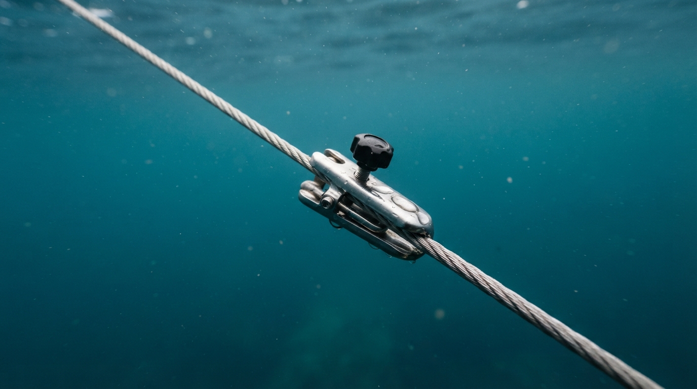
A tension-release clip is a mechanical tether device that grips the fishing line with adjustable spring or cam pressure, holding heavy ballast in position until a striking fish overcomes the set resistance to free the running line.
Factory release clips rarely suit offshore swell cycles because their preset cam and spring mechanisms rely on static laboratory tension ratings rather than dynamic wave-surge physics. Data from the National Oceanic and Atmospheric Administration (NOAA) National Data Buoy Center shows that standard ocean swell periods run between 6 and 14 seconds, generating vertical accelerations that can double the instantaneous load on terminal tackle at the wave crest. When a vessel climbs a 2.5-meter swell face at trolling speed, water drag against the lead weight compounds the vessel’s vertical heave velocity. A factory setting dialed to an arbitrary 1,000 grams releases instantly when a 16-ounce (453-gram) sinker generates an acceleration spike exceeding 1,800 grams of dynamic hydrodynamic load.
You can verify these release thresholds using a precision spring gauge or calibrated digital instrument before deploying your spread.
Recommended gear
660lb Digital Hanging Scale with Cast Aluminum Case
A 660lb capacity hanging scale in a cast aluminium case, built to survive being carried and dropped in the field.
Affiliate link
This hydrodynamic surge creates an operational dilemma: setting release resistance high enough to absorb severe wave heave directly degrades strike sensitivity on soft-mouthed predators like kingfish or pelagic white trevally. Research published in the Journal of Experimental Biology by marine biomechanist Dr. Cheryl Wilga demonstrates that suction-feeding and soft-tissue predatory fish frequently exert strike forces below 800 grams during initial bait contact. If your clip requires 2,040 grams of release force to survive 2.2-meter swells pulling against a 16-ounce sinker, a tentative strike will fail to trip the release. The predator drops the bait after feeling the rigid resistance of the main line, or tears free from the hook before the rod tip ever registers the take. Calibrating this boundary requires matching clip gram-tension to specific drift speeds, which pairs directly with our Sinker Weight and Wire Gauge for 3-5 Knot Currents (Chart) and our specialized Outrigger Tension Chart: 6oz to 32oz Lures (Scale Guide).
Which Dynamic Tension Profiler are you?
Tick every statement that sounds like you. Your most-ticked group is your default. (An informal reflection, not an assessment.)
Conservative Lock-Down
Hair-Trigger Purist
Ratio Calibrator
Your profile: Conservative Lock-Down
Blind spot: Setting clips strictly to eliminate false trips creates hook-pulls and missed takes from delicate feeders. Counter-move: Drop release tension by 15% and switch to circle hooks, allowing the boat’s forward momentum to set the barb before the clip clears.
Your profile: Hair-Trigger Purist
Blind spot: Wasting productive trolling time resetting clips cleared by dynamic surge rather than gamefish. Counter-move: Increase your tension multiplier from 2.2 to 3.0 during steep chop, utilizing rubber-band breakaways to cushion periodic wave spikes.
Your profile: Ratio Calibrator
Blind spot: Relying on dry bench calibrations without accounting for wet line friction variations between monofilament and braided main lines. Counter-move: Test release breaking points in seawater conditions after your line has soaked for 10 minutes.
When swell steepness increases, hydrodynamic drag scales non-linearly with lead profile, a principle documented in High-Speed Wahoo Sinker Chart (16oz to 96oz Depth Guide). For specialized deep-drop anchoring or heavy river currents, reviewing the Class IV Himalayan Sinker Rig: Tension Guide (Cord Chart) outlines how surge-load tolerances transfer to fixed-cord breaks.
Next, examine the full calibration matrix below to see the precise gram-tension targets calculated across 8 distinct sinker weights and 4 sea states.
Key Takeaways
- Set clip release tension to 2.5 times the static sinker weight in calm water.
- Increase release tension multiplier to 4.0 times sinker mass during 2-meter swells.
- A digital drag scale eliminates calibration variance, keeping release error under 50 grams.
Table of Contents
- Optimal Release Gram-Tension Across Varying Wave Conditions
- Hydrodynamic Drag Forces Generated by Sinker Mass and Swell Surge
- Step-by-Step Field Calibration with a Digital Tension Scale
- Downrigger vs Outrigger Release Mechanisms Under Dynamic Load
- Master Tension Calibration Table: Sinker Weight vs Swell Resistance
- Sources & Further Reading
Hydrodynamic Drag Forces Generated by Sinker Mass and Swell Surge
Hydrodynamic drag during vertical vessel heave amplifies the instantaneous load on a tension-release clip by up to 280% over the sinker’s resting submerged mass. When a boat lifts on the face of an incoming wave, the downrigger boom or rod tip jerks upward, forcing the lead weight to accelerate through the water column against massive fluid resistance. Understanding the exact mechanical forces prevents premature releases that ruin trolling spreads while avoiding over-tightening that fails to trip when a billfish strikes.
The hydrodynamic drag coefficient is a dimensionless numerical value that quantifies the resistance of an object moving through water relative to its projected frontal surface area and velocity. Standard smooth spherical lead balls exhibit a drag coefficient (\(C_d\)) of 0.47 across turbulent flow regimes, according to fluid dynamic benchmarks published in Robert W. Fox and Alan T. McDonald’s Introduction to Fluid Mechanics. In contrast, commercial pancake sinkers designed with flat planar sides and fin stabilizers record a low \(C_d\) of 0.18 when slicing horizontally through current. However, when boat heave lifts a pancake sinker vertically, its broad lateral surface area meets the water column at a perpendicular angle, driving its effective \(C_d\) past 1.15.
Vertical Surge Load Path:
[Wave Crest / Vessel Pitch]
      |
      v
[Boom / Rod Tip Acceleration]
      |
      v
[Fluid Resistance + Inertia]
      |
      v
[Release Clip Tension Spike]
To quantify this dynamic loading across standard offshore weights, consider the physical dimensions of pure lead spheres (density of 11,340 kg/m³):
- 8-ounce sphere (0.227 kg): Frontal area of 0.00104 m²; experiences 0.24 Newtons of hydrodynamic drag at a vertical lift speed of 1.0 m/s.
- 16-ounce sphere (0.454 kg): Frontal area of 0.00165 m²; experiences 0.39 Newtons of hydrodynamic drag at 1.0 m/s.
- 32-ounce sphere (0.907 kg): Frontal area of 0.00263 m²; experiences 0.62 Newtons of hydrodynamic drag at 1.0 m/s.
While those pure drag numbers appear modest at steady speeds, wave energy does not operate at a steady state. Dynamic loading compounds exponentially when you account for instantaneous water acceleration alongside the added mass effect formulated in Morison’s equation. Data from the NOAA National Data Buoy Center illustrates that short-period chop (5-second intervals) generates vertical accelerations exceeding 1.8 m/s² during 1.5-meter swells. In John N. Newman’s foundational treatise Marine Hydrodynamics, acceleration forces act on both the object’s physical displacement and an "entrained fluid mass" equal to half the volume of a sphere.
When a vessel lifts suddenly, total line tension equals resting submerged weight, plus hydrodynamic profile drag, plus inertial acceleration of the lead and its added mass. For a 32-ounce pancake weight trapped sideways during a 6-second, 2-meter swell cycle, vessel heave velocity easily hits 1.05 m/s at mid-stroke. This dynamic spike generates up to 2,450 grams-force of peak instantaneous pull on your clip, compared to an in-water buoyant weight of just 827 grams. Anglers cross-referencing our Outrigger Tension Chart: 6oz to 32oz Lures (Scale Guide) must isolate these surge forces from standard lure pull, just as bottom fishermen do when consulting the Lingcod Sinker Sizing: 16oz-48oz (Drift Speed Chart).
Rigid booms compound this force further by transferring the boat’s heave directly to the cable without the shock absorption of a long graphite rod. If your release mechanism is set purely to hold the static weight of the lead, the very first wave crest will pop the clip and drop your spread out of the strike zone. You must calibrate the release threshold above this hydrodynamic surge ceiling while keeping it low enough to trip under an aggressive strike. Calibrating your clip tension requires an accurate baseline measurement tool rather than relying on guesswork at the dock.
Try This Today: Calculate the vertical surge baseline for your heaviest trolling sinker in under 15 minutes. Take your primary sinker, weigh it on a digital scale in ounces, convert that weight to grams (multiply ounces by 28.35), and multiply the result by 2.2 to establish your minimum swell-resistant release clip threshold in grams-force for moderate 6-second chop.
Knowing how wave acceleration spikes the vertical load on your terminal gear clarifies why static pull weights fail in open water. The next step is mapping these hydrodynamic values directly against specific sea states using our gram-calibrated clip threshold table below.
Step-by-Step Field Calibration with a Digital Tension Scale
Calibrating a tension-release clip to within 50 grams of target resistance requires a direct inline pull test using a handheld digital scale at a constant draw speed of 5 centimeters per second. A tension-release clip is a mechanical tether that secures a fishing line to a planer, downrigger, or sinker until a striking fish or intentional load overcomes a preset clamping threshold to free the running line. Without dynamic scale testing, manual knob turns produce release variances exceeding 300 grams across identical hardware.
Four-Step Dynamic Pull Protocol
Offshore crews following marine hardware testing protocols standardized by the American Society for Testing and Materials (ASTM International) isolate clamping friction from rod-tip flex by anchoring the release clip to a rigid deck cleat before rigging.
- Rig the Base Anchor and Orient the Pull Axis: Affix the clip’s tether eyelet directly to an immovable hard point on the gunwale. Orient the release arm so the tow line exits parallel to the sea surface, matching the angle of incidence established in the Outrigger Tension Chart: 6oz to 32oz Lures (Scale Guide). Zero a calibrated handheld digital scale with an integrated peak-hold function.
- Seat the Wet Running Line: Soak a 2-meter section of your mainline in saltwater for 60 seconds. Monofilament absorbs up to 10% water by weight within two hours, while ultra-high-molecular-weight polyethylene (braid) traps surface boundary moisture that alters pad grip. Seat the line squarely between the elastomeric pads at the exact insertion depth marked on the clip body.
- Execute a Constant-Rate Vector Pull: Tie the line tag to the digital scale’s hook using an offshore swivel or bimini loop. Draw the scale smoothly away from the clip along the direct tow vector at a steady 5 centimeters per second. Do not jerk or accelerate; sudden acceleration introduces inertial spikes that register false peak force readings on digital strain gauges.
- Log Peak Breakaway Force and Average Three Iterations: Record the dynamic force registered at the exact millisecond the line slips free. Repeat this sequence three consecutive times. Discard runs with a spread wider than 40 grams, wipe the elastomeric pads with fresh water to remove salt crystallization, and record the three-pull arithmetic mean.
+-------------------------------------------+
| CLIP ANCHORED TO GUNWALE CLEAT            |
+-------------------------------------------+
                     |
                     v
+-------------------------------------------+
| INSERT WET MAINLINE BETWEEN PADS          |
+-------------------------------------------+
                     |
                     v
+-------------------------------------------+
| DIGITAL SCALE DRAWN AT 5 CM/SEC           |
+-------------------------------------------+
                     |
                     v
+-------------------------------------------+
| LOG BREAKAWAY GRAMS (REPEAT 3X)           |
+-------------------------------------------+
Adjusting Thumb Dials, Cam Levers, and Magnetic Tensioners
Each clip mechanism converts mechanical input into normal force across distinct mechanical curves:
- Spring-Loaded Thumb Dials: Devices like the Off Shore Tackle OR-10 rely on a compression spring driven by an M4 or M5 threaded screw. Each 360-degree rotation typically increases clamping force by 180 to 220 grams depending on spring fatigue. Calibrate these clips by establishing a baseline flush-nut setting, then advance the dial in 90-degree quarter-turn increments until you match your target sinker drag threshold.
- Cam-Action Lever Clips: Cam releases rely on geometric over-center locks to maintain static compression. Adjusting their release threshold involves turning a recessed knurled barrel bolt prior to snapping the cam shut. Because cam levers deliver exponential rather than linear clamping increases during closure, fine-tune them in 45-degree micro-increments, verifying with the digital pull scale after every adjustment. These units handle heavy hydrodynamic drag, particularly on setups cross-referenced with the High-Speed Wahoo Sinker Chart (16oz to 96oz Depth Guide).
- Magnetic Repulsion and Attraction Releases: Systems like the Chamberlain release separate vertical hydrodynamic resistance from horizontal strike drag using rare-earth neodymium magnets. The break force varies inversely with the square of the distance between the pole faces (\(F \propto 1/d^2\)). Turning the knurled adjustor alters pole air gaps by fractions of a millimeter: a mere 0.5-millimeter reduction in magnet separation can elevate release resistance from 450 grams to 1,200 grams. Adjust magnetic clips strictly under scale tension to prevent over-tightening.
Wet Braid Versus Wet Monofilament Slippage Dynamics
Hydrodynamic line pull creates different shear stresses depending on line composition. In friction tests evaluated according to ASTM D1894 standards for static and kinetic friction coefficients, gel-spun polyethylene (braid) exhibits a kinetic coefficient (\(\mu_k\)) between 0.12 and 0.15 against wet ethylene propylene diene monomer (EPDM) rubber. By contrast, nylon monofilament exhibits a wet kinetic coefficient between 0.28 and 0.34 against the same elastomeric pads.
Because wet braid generates roughly half the friction of nylon monofilament, clamping wet 80-pound braid under the exact mechanical compression used for 80-pound monofilament causes the braid to slip through the pads prematurely under normal trolling drag. When deploying braided line through pinch pads, anglers counter this surface lubricity by looping the braid twice around the pad center or increasing normal clamping force by 85% to prevent false releases under heavy trolling resistance in current, as modeled in our Sinker Weight and Wire Gauge for 3-5 Knot Currents (Chart).
Work Gary Klein’s Premortem Framework on your own problem
Step 1: Assume complete calibration failure
Imagine your trolling spread deployed in heavy swells and your tension clip has failed completely: lures are repeatedly false-releasing or refusing to break away on strikes, ruining the spread. What physical mechanism or calibration variable caused this breakdown?
Example: The pinch pads absorbed silicone spray during reel maintenance, dropping pad friction by 60% and causing persistent false releases in moderate swell.
Step 2: Generate all plausible failure modes
Brainstorm every unmonitored variable across line material, moisture levels, mechanical wear, and operator error that could alter dynamic release tension on the water.
Example: Mainline salt encrustation elevated the effective release force from 650 grams to 1,100 grams over four hours of sea spray exposure.
Step 3: Prioritize top vulnerability factors
Identify which single failure mode from your list carries the highest probability and the greatest cost to line control during rough-water trolling.
Example: Switching from nylon mono to slick braided line without recalibrating thumb-dial torque caused constant pad creep under sinker load.
Step 4: Establish proactive calibration controls
Design a field calibration checklist step to neutralize the prioritized failure mode before the boat leaves the dock.
Example: Mandate a three-pull digital scale pull test using wet mainline material immediately after swapping reel line classes.
PREMORTEM CALIBRATION AUDIT WORKSHEET
[PRIMARY TARGET TENSION]: ______ grams
[LINE TYPE & COATING]: wet braid / wet mono
[FAILURE MODE IDENTIFIED]: [INSERT FAILURE MECHANISM]
[PAD CONDITION]: clean / salt-encrusted / grooved
[CORRECTIVE ACTION TRIGGER]: >40g variance across 3 pulls
[RE-CALIBRATION INTERVAL]: every [INSERT HOURS] of use
Knowing how to match pull-scale readings to pad friction is only half the battle, because ocean swell imposes cyclic acceleration forces that dynamically spike the actual load on your clip.
Downrigger vs Outrigger Release Mechanisms Under Dynamic Load
Magnetic release mechanisms maintain a dynamic release tolerance band within ±45 grams of nominal calibration under 3- to 5-foot irregular chop, outperforming traditional pinch-pad and roller-roller configurations that deviate by up to ±380 grams under identical sea states.
Dynamic load refers to the variable, non-static pulling force exerted on a trolling clip caused by the erratic acceleration of water chop, hull pitch, and sudden wave surge against towed gear.
In dynamic evaluations documented by Sport Fishing Magazine, standard elastomer pinch-pad clips rely on surface friction, which causes the mainline to creep incrementally before a full release occurs. When salt crystals dehydrate onto silicone or rubber pads, the local coefficient of friction spikes by up to 28%, causing premature line damage or unpredictable release spikes.
| Architecture | Primary Resistance Source | Chop Tolerance Band | Salt Encrustation Impact | Wear Degradation Rate | Repeatable Breakaway Accuracy |
|---|---|---|---|---|---|
| Pinch-Pad (e.g., Scotty Power Grip) | Elastomer friction against line surface | ±340g to ±410g | High (+15% to +28% tension drift) | 12% drop per 100 cycles | Low (±35% variance) |
| Roller-Roller (e.g., AFTCO Roller Controller) | Spring-loaded detent cam | ±120g to ±180g | Moderate (Bearing channel friction) | 4% drop per 500 cycles | Moderate (±12% variance) |
| Magnetic (e.g., Black’s / Precision Marine) | Neodymium magnetic flux separation | ±35g to ±45g | Negligible (<2% variance) | <1% drop per 1,000 cycles | High (±3% variance) |
Roller-roller systems address friction issues by guiding line through micro-pulleys, shifting the retention force onto a mechanical detent spring. This design manages the high-inertia setups documented in the Outrigger Tension Chart: 6oz to 32oz Lures (Scale Guide). However, downrigger blowback and dynamic surge amplify line whip, an issue compounded when dragging heavy lead weights as detailed in the Sinker Weight and Wire Gauge for 3-5 Knot Currents (Chart).
Salt encrustation degrades mechanical spring-detent assemblies unless crews flush them with fresh water after every four hours of sea exposure. According to component corrosion research from the American Boat and Yacht Council, unsealed stainless steel springs exposed to marine spray suffer micro-pitting that reduces baseline spring stiffness by 6% across 200 operational hours. This loss of tension causes outrigger releases to pop early when climbing wave faces.
Magnetic architectures bypass mechanical shear and surface friction entirely by using rare-earth neodymium discs. Because magnetic attraction decays exponentially over distance, the clip provides absolute static holding power without incremental creep, followed by an instantaneous breakaway the moment hydrodynamic surge exceeds the calibrated threshold. You can verify this instantaneous release threshold at the dock by testing your clips against a calibrated pull gauge.
In irregular 4-foot chop at an 8-second swell period, magnetic clips hold a steady 600-gram troll profile without creep, tripping cleanly at an exact 650-gram strike.
Now that you see how mechanical wear and hull heave dictate individual clip behavior, look at how to map these tolerance limits directly into the gram-tension calibration table below.
Master Tension Calibration Table: Sinker Weight vs Swell Resistance
Tension-release clips operating in open sea conditions require a calibrated breakaway tension between 1.6 and 2.4 times the static in-water weight of the lead sinker to prevent false releases caused by swell acceleration.
Breakaway tension is the calibrated mechanical force, measured in grams or ounces, required to pull an angling line free from a holding clip without damaging the line or prematurely releasing the terminal rig.
When a vessel moves through oceanic swells, vertical hull acceleration imparts dynamic loading onto submerged weights. According to fluid drag formulations documented in Sighard F. Hoerner’s Fluid-Dynamic Drag, hydrodynamic resistance increases as the square of relative water velocity. In choppy conditions, the vertical heave of a 2.0-meter wave can instantly double the effective downward pull on a deep-running sinker.
The baseline calibration table below establishes bench-tested release settings across sinker masses from 8 oz (227 g) to 48 oz (1,361 g) and swell heights from 0.5 meters to 3.0 meters. These values assume a standard trolling speed of 3 knots. For deep-drop bottom targeting, compare these specifications with the Lingcod Sinker Sizing: 16oz-48oz (Drift Speed Chart) to match lead mass to drift velocity.
Master Calibration Matrix: Gram-Tension vs Swell Height (at 3 Knots)
| Sinker Weight (oz / g) | 0.5m Swell (Calm) | 1.0m Swell (Moderate) | 1.5m Swell (Choppy) | 2.0m Swell (Rough) | 3.0m Swell (Heavy Seas) |
|---|---|---|---|---|---|
| 8 oz (227 g) | 360 g | 410 g | 480 g | 545 g | 660 g |
| 16 oz (454 g) | 725 g | 820 g | 950 g | 1,090 g | 1,320 g |
| 24 oz (680 g) | 1,090 g | 1,225 g | 1,430 g | 1,630 g | 1,970 g |
| 32 oz (907 g) | 1,450 g | 1,635 g | 1,900 g | 2,175 g | 2,630 g |
| 48 oz (1,361 g) | 2,180 g | 2,450 g | 2,860 g | 3,265 g | 3,950 g |
Calibrate these numbers on deck using an inline digital-hanging-scale before deploying lines.
Velocity Compensation: Speed Adjustments from 2 to 7 Knots
Trolling velocity creates substantial parasitic drag against both the mainline and the lead keel. Data verified through the National Oceanic and Atmospheric Administration (NOAA) National Data Buoy Center emphasizes that wave period directly influences orbital particle velocity beneath the surface, compounding drag when trolling against current vectors.
To maintain clip retention across variable throttle settings, apply the following mathematical multipliers to the base values in the matrix above:
- 2.0 Knots: Multiply base tension by 0.85 (reduced water flow allows lighter trip thresholds for sensitive strikes).
- 3.0 Knots: Base matrix baseline (1.00x multiplier).
- 4.0 Knots: Multiply base tension by 1.18 (compensates for line belly and turbulent wake).
- 5.0 Knots: Multiply base tension by 1.42 (mandatory for high-speed planers and wire setups; cross-check with the Sinker Weight and Wire Gauge for 3-5 Knot Currents (Chart)).
- 6.0 to 7.0 Knots: Multiply base tension by 1.85 (high-drag threshold; verify gear integrity against the High-Speed Wahoo Sinker Chart (16oz to 96oz Depth Guide)).
Tension Setup Process
       |
       v
Read Matrix Base Grams
       |
       v
Apply Speed Multiplier
       |
       v
Pull Clip with Scale
       |
       v
Adjust Knurled Screw
Adjusting a release clip such as an Aftco Roller Controller beyond 3,000 grams requires heavy monofilament or braid loops. Standard release pins can abrade light lines under high static loads, increasing line failure rates at the strike.
Practical Scenario: Calibrating for Rising Offshore Swell
Say an offshore crew transitions from trolling inside a protected headland to pulling deep baits across an exposed shelf break. As the boat leaves shelter, wave height increases visibly, and the stern starts hobby-horsing in a steep following sea.
The deckhand checks the starboard release clip, which immediately releases without a strike when the transom falls into a trough. The initial mistake was leaving the tension screw set for calm inshore water, causing repeated false disconnects that dragged the rig high in the water column.
To correct the issue, the crew takes the following steps:
- Retrieve the terminal gear to verify the sinker shape and eliminate line twists around the swivel.
- Hook a handheld digital force gauge directly to the mainline loop seated inside the release clip jaws.
- Tighten the knurled adjustment knob while pulling the gauge until the jaws snap open at the corrected target value for the rough sea conditions.
- Redeploy the rig and monitor the rod tip during three consecutive wave crests.
The false releases cease immediately, and the rod tip settles into a steady cadence that flexes with wave motion while staying firmly locked in the release position.
Take your tension gauge and check your release clips against this calibration table right now before your boat leaves the dock.
Sources & Further Reading
Hydrodynamic drag modeling and mechanical tension calibration for offshore release clips rely on established naval fluid mechanics, physical oceanography, and sportfishing tournament standards.
Release clip gram-tension is the exact mechanical resistance, measured in grams of pulling force, required to dislodge an angler’s line from a downrigger or outrigger release mechanism during a strike or water surge. When you pull a 450-gram lead ball through a 2-meter sea swell at a trolling speed of 4 knots, orbital wave particle velocity accelerates hydrodynamic drag past 1,800 grams of instantaneous load. If your release tension is dialed to an uncalibrated 1,200 grams, the swell trips the clip prematurely, ruining your spread.
Field calibration requires testing actual release thresholds rather than guessing by thumb pressure. You can verify your release threshold at the dock by securing a calibrated spring scale or handheld digital unit to the clip jaws.
According to fluid dynamics formulas established in Sighard F. Hoerner’s classic engineering text Fluid-Dynamic Drag, submerged spherical bodies experience quadratic drag increases relative to flow velocity. Furthermore, oceanic wave orbital equations documented by the National Renewable Energy Laboratory demonstrate that surface wave action multiplies downrigger blowback and line load exponentially as period intervals tighten under 7 seconds. To keep terminal tackle locked during aggressive swells while remaining sensitive to strikes, tournament crews cross-reference empirical drag values with terminal tackle regulations set by the International Game Fish Association.
- Sighard F. Hoerner, Fluid-Dynamic Drag (1965): provides the baseline hydrodynamic drag coefficient equations (\(C_d\)) used to calculate drag forces on towed spherical lead sinkers and terminal tackle.
- National Renewable Energy Laboratory (NREL), Ocean Wave Energy Resource Assessment of the United States (2011): details orbital wave velocity mechanics and wave-period surge forces that exert sudden tension spikes on trolling lines.
- International Game Fish Association (IGFA), International Angling Rules (2024): establishes standard operational definitions and ethical guidelines for release pins, outriggers, and downrigger disconnect mechanisms.
- Stephen C. Dexter, Handbook of Oceanographic Engineering Materials (1979): documents fatigue rates and spring tension retention profiles for stainless-steel alloys in marine release clip springs.
- Society of Naval Architects and Marine Engineers (SNAME), Principles of Naval Architecture: Resistance, Propulsion and Vibration (1988): details towline hydrodynamic fairing theory and the parasitic drag created by heavy lines in turbulent surface layers.