0° to 24° Transducer Deadrise Chart (Selection Guide)
⏱ 26 min read
Acoustic Alignment Rules for V-Bottom Boat Hulls
Transducer deadrise compensation matches your hull’s transverse V-angle to project sonar pulses vertically toward the seabed, preventing signal attenuation and target distortion. A pocket mount recesses the ceramic element flush into the keel to maximize vessel speeds above 30 knots without hydrodynamic drag, while an external fairing block projects the face below the hull’s aerated boundary layer to maintain clean acoustic returns at depths exceeding 1,000 feet. Selecting between them depends on your hull’s deadrise angle, vessel operating speed, and trailer bunk clearance.
Deadrise angle is the measurement in degrees of the upward V-shaped slope of a boat’s hull from the keel line out to the chine. This angle determines both hull wave slicing capability and the angular compensation required for downward-firing marine electronics.
Beam Geometry and Signal Attenuation
When an uncompensated transducer sits on a 15° deadrise hull, its acoustic cone fires 15° away from true vertical. Acoustic engineering documentation from Airmar Technology Corporation confirms that a sonar beam tilted more than 3° off-axis causes severe return signal degradation. Instead of reflecting sound energy straight back to the ceramic receiver, the seabed acts as an acoustic mirror, deflecting the primary pulse away from the boat.
This angular error distorts target separation. As the sonar pulse hits the bottom obliquely, the leading edge of the acoustic cone strikes the bottom before the trailing edge. This time differential artificially widens the bottom return echo, which masks fish holding within 3 to 6 feet of the bottom substrate. When targeting structure-oriented species or tracking terminal tackle via a Slow Pitch Jig Weight Chart: 100 to 800 Feet (Chart), an unaligned transducer causes you to lose bottom-lock tracking completely.
       OFF-AXIS ACOUSTIC GEOMETRY

           [ Hull Plate: 18° ]
               \       /
                \ [X] <--- Unaligned Element
                 \   \
                  \   \ 18° Tilt
                   \   \
                    v   v

   False Bottom <--- [ Seabed ] ---> Echo Reflected
   Echo Smeared                     Away From Hull
The Critical 3° Tolerance Window
Marine transducer elements tolerate up to 3° of total mechanical misalignment before return sensitivity drops below acceptable operational thresholds. Beyond 3°, the geometric center of the acoustic footprint shifts significantly relative to vessel position, as calculated below:
\(\text{Beam Footprint Offset} = \text{Depth} \times \tan(\theta_{\text{tilt}})\)
At an operational depth of 600 feet, a 3° tilt displaces the center of your sonar cone by 31.4 feet to port or starboard. With a narrow 6° high-frequency beam (common on 1 kW and 2 kW deep-water elements), a 3° tilt shifts the acoustic center by 50% of its entire cone width. On a wide 25° beam, that same 3° error represents only a 12% shift from the central axis. Narrow-beam CHIRP transducers therefore demand strict deadrise compensation within 1° of the hull’s actual deadrise angle at the mounting location.
Mounting Geometries: Pocket Mount vs. Fairing Block
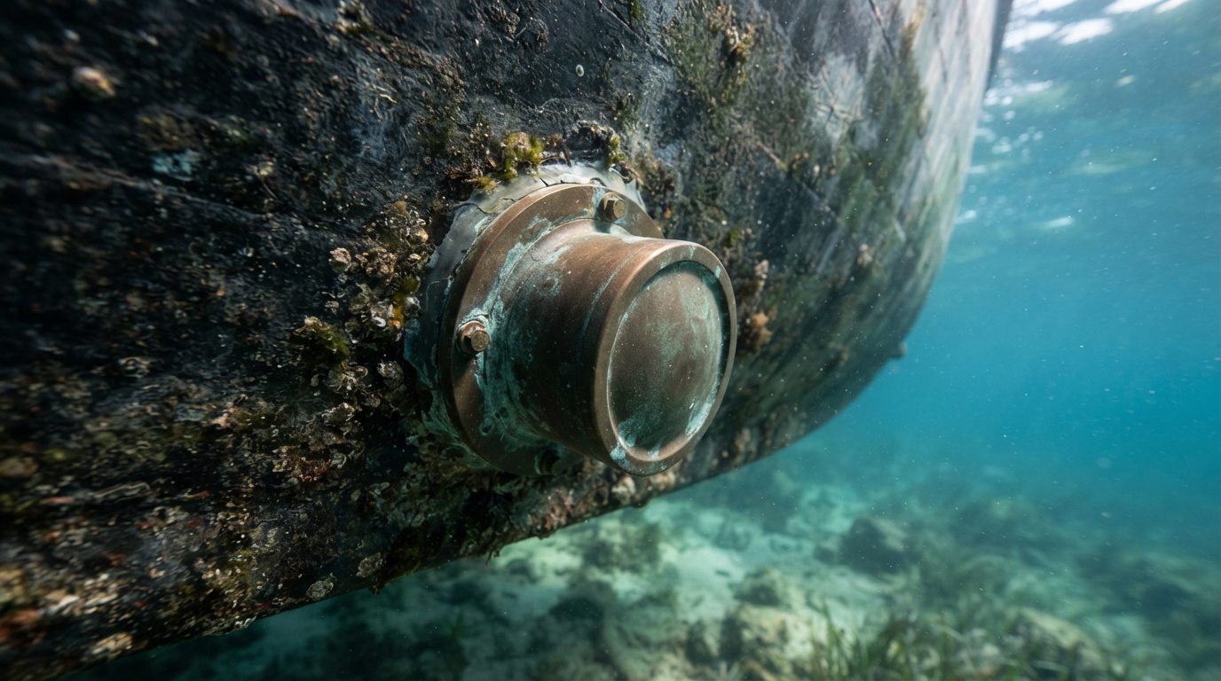
Choosing between a flush pocket mount and a high-speed fairing block requires balancing acoustic clarity against fluid dynamics. High-speed center consoles cruising at 35 to 55 knots produce immense shear forces on hull-mounted projections. A high-performance fairing block extending 2.5 inches below the gelcoat generates localized drag, increases fuel burn, and introduces mechanical stress on the bronze mounting stem. Furthermore, extended fairings regularly interfere with trailer bunks and commercial boatyard travel lifts.
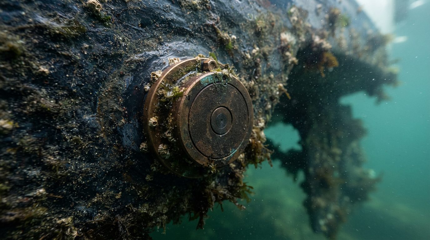
Pocket mounting solves hydrodynamic drag by recessing the ceramic housing entirely within a molded fiberglass cavity flush with the running surface. The trade-off centers on signal clarity at speed: pocket mounts sit inside the hull’s boundary layer, where aerated water flowing along the running surface can cross the transducer face, causing acoustic clutter and lost bottom contact above 22 knots. Fairing blocks push the acoustic window down through this boundary layer into clean, non-aerated laminar water, providing unmatched target resolution at offshore depths.
- Measure deadrise at the exact mounting location using a digital inclinometer while the boat rests level on its trailer or blocking.
- Select a tilted-element or pocket mount for vessels with cruising profiles exceeding 32 knots to prevent hydrodynamic drag and hull shear.
- Specify a high-performance fairing block if your target fishery requires tracking bottom structure in water deeper than 800 feet at displacement speeds.
- Verify trailer bunk, roller, and travel-lift sling placement to ensure a minimum of 4 inches of clearance around any projected fairing block.
- Match the transducer internal tilt (0°, 12°, or 20°) to ensure the net mechanical misalignment remains strictly within the 3° operational window.
Review the deadrise measurement protocols in the next section to verify whether your keel profile requires an internal tilted ceramic array or an external cast fairing.
Key Takeaways
- Tilted-element transducers accommodate hull deadrise between 0° and 24° within an allowable 3° acoustic offset margin.
- Pocket keel mounts eliminate hull drag and bunk interference but require custom fiberglass recasting.
- High-speed fairing blocks drop the transducer face 1 to 3 inches below turbulent aerated boundary water.
- Exceeding 3° of uncompensated tilt reduces returned acoustic target power to the receiver by up to 50%.
Table of Contents
- Acoustic Alignment Rules for V-Bottom Boat Hulls
- Deadrise Compensation Chart for 0° Through 24° Hulls
- Pocket Flush Mounting Performance and Laminar Flow Dynamics
- High-Speed Fairing Blocks and Boundary Layer Penetration
- Pocket Mount Versus Fairing Block Technical Comparison
- Six-Step Deadrise Measurement and Transducer Selection Procedure
- The Offshore Rigging Decision Matrix and Installation Checklist
- Sources & Further Reading
Deadrise Compensation Chart for 0° Through 24° Hulls
Deadrise angle is the vertical slope measured in degrees between the horizontal waterline plane and the upward angle of a boat’s hull bottom toward the chine. Installing a tilted-element transducer or fairing block aligns the internal piezo-ceramic elements directly perpendicular to the seabed, preventing target distortion, false depth readings, and signal attenuation.
According to technical specifications published by Airmar Technology Corporation, a tilted element maintains acoustic symmetry only when the vessel’s running deadrise falls within a narrow ±3° window of the transducer’s internal tilt. Operating outside these design windows skews the acoustic cone, splitting acoustic energy into parasitic side lobes that degrade bottom tracking at speeds above 15 knots.
| Measured Hull Deadrise | Recommended Transducer Tilt | Effective Beam Alignment Deviation | Operational Status | Pocket Mount / Fairing Alternative |
|---|---|---|---|---|
| 0° to 3° | 0° Fixed Tilt | 0.0° to 3.0° | Optimal | Flush pocket mount |
| 4° to 7° | 0° Fixed Tilt | 4.0° to 7.0° | Acceptable (Minor asymmetry) | Custom pocket bevel |
| 8° to 10° | 12° Fixed Tilt | 2.0° to 4.0° | Acceptable (Boundary zone) | High-speed fairing block |
| 11° to 15° | 12° Fixed Tilt | 0.0° to 3.0° | Optimal | Custom pocket bevel |
| 16° to 18° | 20° Fixed Tilt | 2.0° to 4.0° | Acceptable (Boundary zone) | High-speed fairing block |
| 19° to 24° | 20° Fixed Tilt | 0.0° to 4.0° | Optimal | Pocket cavity or dual paired split |
| > 24° | N/A (Exceeds tilt capacity) | > 4.0° | Critical Dead Zone | Split-pair system (e.g., B175L/H pair) |
Hull angles falling precisely at 7.5° or 15.5° represent mechanical dead zones for single tilted-element transducers. When mounting on a 15.5° deadrise, selecting either a 12° or a 20° element generates 3.5° of permanent acoustic tilt, which projects a 1-kilowatt beam off-axis by roughly 37 feet at a depth of 600 feet. When targeting structure for deep bottom operations, such as positioning over drop-offs detailed in our Slow Pitch Jig Weight Chart: 100 to 800 Feet (Chart), this deflection produces depth errors that misplace the vessel relative to target contours.
Keel-Offset and Boundary Clearance Calculations
Mounting locations must balance acoustic orientation with boundary-layer hydrodynamics. The American Boat and Yacht Council (ABYC) standard H-27 dictates that through-hull fittings must maintain mechanical integrity without inducing localized hull delamination under dynamic hydraulic pressure.
Aeration is the primary failure mode in high-speed sonar tracking. Lifting strakes, raw-water pick-ups, and stepped hull vents shed aerated vortex trails that travel directly aft along the hull surface.
FLOW CLEARANCE GEOMETRY:
Keel Centerline
 |
 |<-- 6" to 12" Lateral Offset -->|
 |                                 [X] Transducer
 |
 Strake / Step Aeration Line ===== (Keep clear)
 |                                 Min. 4" outboard
To calculate the minimum lateral offset from any forward strake or step vent, apply the divergence equation established in hydrodynamic testing:
\(\text{Minimum Lateral Distance} = D_{\text{vent}} + (L_{\text{aft}} \times 0.087)\)
In this equation, \(D_{\text{vent}}\) represents the physical width of the strake edge or vent pocket in inches, and \(L_{\text{aft}}\) is the longitudinal distance running aft from the turbulence source to the transducer face. If a stepped vent measures 3 inches wide and the transducer sits 36 inches aft of the step break, the transducer face requires a minimum clear lateral offset of 6.13 inches outboard or inboard of the aerated wash track.
On deep-V hulls (20° to 24° deadrise), transducers must sit a minimum of 6 inches, and preferably 10 to 12 inches, away from the keel centerline to avoid displacement aeration generated by the stem entry slice at speeds exceeding 22 knots.
Which hull-matching approach fits your vessel?
Tick every statement that sounds like you. Your most-ticked group is your default. (An informal reflection, not an assessment.)
Solid Deep-V Purist
Stepped-Hull Specialist
Commercial-Grade Deep Dropper
Your profile: Solid Deep-V Purist
Blind spot: Relying on a single 20° tilted element on a 24° deadrise hull leaves a 4° deadrise mismatch that degrades high-frequency target discrimination. Counter-move: Install a dual-frequency split-pair transducer system wired through an internal diplexer to balance load across both port and starboard running surfaces.
Your profile: Stepped-Hull Specialist
Blind spot: Installing a through-hull element aft of a step places the acoustic window directly into ventilated, entrained aerated flow. Counter-move: Relocate the transducer forward of the first ventilation step, adjusting deadrise compensation for the steeper running angle found at that forward station.
Your profile: Commercial-Grade Deep Dropper
Blind spot: Large high-speed fairings create rotational torque and can trip trailer bunks or lift straps during routine dry-dock operations. Counter-move: Machine a recessed pocket cavity directly into the hull laminate to set the transducer flush while keeping the ceramic face horizontal to the seabed.
Understanding these mechanical tolerances establishes the baseline geometry for acoustic clarity, but physical hull construction dictates how you must fasten and bed the housing to prevent structural failure under load.
Pocket Flush Mounting Performance and Laminar Flow Dynamics
Pocket flush mounting preserves laminar flow across high-speed hulls by recessing the transducer flush with the running bottom, eliminating parasitic hydrodynamic drag and the turbulent boundary-layer separation caused by external fairing blocks. Laminar flow is the smooth, uninterrupted movement of fluid layers sliding parallel past a vessel’s hull without cross-current mixing or chaotic micro-vortices disrupting the acoustic path. When you mount a 2 kW or 3 kW transducer—such as an Airmar PM275LHW—inside a custom pocket, the transducer face sits within 0.8 mm (1/32 inch) of the true hull plane. Technical documentation from Airmar Technology Corporation emphasizes that maintaining this tolerance prevents the acoustic window from acting as a physical scoop or trip-step at cruising speeds exceeding 30 knots.
If a pocket recess is molded or routed too deep, it creates a hydro-acoustic issue known as cavity resonance. When water shears across an unfaired pocket gap deeper than 3.0 mm (1/8 inch), it produces localized pressure differentials and shear-layer vortices that vibrate across the transducer face. Field analysis published by the Society of Naval Architects and Marine Engineers (SNAME) confirms that open recesses generate unsteady pressure fluctuations that degrade high-frequency sonar returns by up to 14 dB at speeds between 28 and 42 knots. To stop this acoustic interference, fiberglass technicians bed the transducer in structural epoxy and fair the perimeter margins with microballoon-filled vinylester until the hull surface feels completely seamless to the touch.
🔑 Jargon Buster
- Boundary Layer
- The thin stratum of water immediately adjacent to a moving hull, where fluid friction reduces velocity relative to the boat. As speed increases, this layer thickens and transitions from smooth fluid to turbulent flow, scattering acoustic ping energy.
- Cavity Resonance
- An acoustic and hydrodynamic phenomenon occurring when water rushes across an open hull recess, producing rapid pressure oscillations and trapped micro-vortices. This turbulence disrupts transducer signal return and generates acoustic noise across the transducer face at cruising speeds.
- Aeration Shadow
- A zone of entrained air bubbles extending downstream from hull features like raw-water intakes, strakes, or steps. When swept across an active transducer face, this micro-bubble curtain reflects high-frequency sonar pings and causes total bottom-signal loss.
Transducer location dictates whether you read bottom at 45 knots or stare at a screen full of surface clutter. Boundary layer thickness increases progressively from the bow entry to the transom, growing from roughly 2 mm at the forefoot to over 35 mm near the stern on a 38-foot offshore center console. You must place flush pocket installations in the forward-running third of the running surface, keeping the face clear of boundary layer growth while ensuring the face stays submerged during hard re-entries. Maintaining continuous bottom tracking at 30 knots allows skippers to pinpoint isolated humps before deploying deep bottom tactics outlined in the Slow Pitch Jig Weight Chart: 100 to 800 Feet (Chart).
      RECOMMENDED TRANSVERSE POSITIONING
=============================================
  STERN <----------------------------- BOW

  [Transom]   [Step 2]   [Step 1]   [Pocket]
     |           |          |          |
     |---Air---->|---Air--->|          |
                                (Solid Water)
  Rule: Minimum 450 mm forward of Step 1
=============================================
Stepped hulls present a severe aeration challenge because their transverse hull breaks intentionally suck down atmospheric air to reduce wetted hull friction. Navigational architects at Michael Peters Yacht Design point out that ventilated steps create an impenetrable curtain of entrained air bubbles directly abaft each relief step. If you install a pocket transducer behind a step, that aeration curtain sweeps under the housing and blinds high-frequency CHIRP signals instantly. You must position the pocket cutout at least 450 mm (17.7 inches) forward of the first hull step, or move outboard of the air trails along a clean planing pad.
       MINIMUM STEP CLEARANCE PROFILE
=============================================
             [Solid Laminar Flow]
                      |
                      v
 Hull Bottom: =======[Pocket]=========\_
                                       \_ [Step]
                      |<-- 450 mm min -->|
                                         \=====
                                      (Aeration)
=============================================
Pocket mounting delivers major mechanical advantages over external high-speed fairing blocks for trailerable center consoles and dry-stack sportfish vessels. A traditional high-speed fairing block projects between 75 mm and 130 mm (3 to 5 inches) below the keel, producing up to 18 kg (40 lbs) of parasitic drag at 40 knots. That projection exposes the bronze stem to catastrophic shearing from bunk trailer crossmembers, dry-stack forklift tines, or submerged flotsam. A flush pocket creates zero parasitic drag, cannot snag trailer bunks during retrieval, and keeps high-value 24-degree deadrise deep-V hulls tracking straight under full throttle.
Calculating the precise cut angle for these pocket recesses requires balancing hull deadrise against transducer beam spread.
High-Speed Fairing Blocks and Boundary Layer Penetration
High-speed fairing blocks maintain bottom tracking at speeds exceeding 30 knots by mechanically displacing the transducer face below the aerated boundary layer of the hull.
The boundary layer is a thin stratum of turbulent, aerated water that clings to the running surface of a boat hull as it moves through the water column, scattering acoustic energy and blinding high-frequency sonar elements. According to hydrodynamic installation documentation from Airmar Technology Corporation, a vessel cruising at 25 knots develops a boundary layer that typically ranges from 0.75 inches to over 1.5 inches in thickness near the midsection.
[ Hull Running Surface ]
========================
~~~~ Turbulent Layer ~~~ (0.75"-1.5")
------------------------
| High-Speed Fairing   |
| Block Assembly       |
------------------------
[ Transducer Face ]
========================
==== Laminar Flow ====== (Undisturbed)
By cutting a high-density urethane fairing block to match the specific deadrise of the hull, the installer positions the face of the transducer into clean, laminar water below this turbulence zone. The cut must be parallel to the keel centerline within a tolerance of 0.5 degrees. If the fairing face pitches up or down even 1.0 degree relative to dynamic waterlines at cruise, cavitation bubbles form across the acoustic window, generating severe ambient acoustic noise.
Securing these massive assemblies to 18° to 24° deep-V hulls introduces extreme mechanical leverage against the hull skin. Airmar installation guidelines specify that large 1 kW to 2 kW fairing assemblies—such as the B260 or B275LHW series—require a secondary anti-rotation bolt to prevent rotational torque from twisting the housing. When a hull runs through an offshore chop at 35 knots, rotational sheer stresses on an unpinned fairing can crack fiberglass laminates or compromise marine sealant barriers.
Torque limits must be strictly observed during installation. For a standard 1.25-inch bronze through-hull stem, tightening torque should not exceed 40 foot-pounds (54 Nm), while the anti-rotation bolt typically seats at 10 foot-pounds. Over-torquing the main nut crushes the internal triangular backing block, which must be cut from the remaining half of the urethane fairing block and mated inside the hull at the inverse angle of the deadrise.
Aligning the internal backing block ensures that the retaining nut seats completely flat against the washer. If the interior backing block is out of plane by more than 2 degrees, lateral loads transfer directly into the threaded bronze stem rather than distributing across the hull laminate. In heavy sea states where crews must deploy safety gear detailed in our Offshore Life Raft Sizing Matrix (Selection Worksheet), the hull experiences repetitive vertical impacts exceeding 3 to 4 Gs. Any uneven stress concentration on an angled through-hull stem can cause catastrophic shear failure.
The acoustic clarity delivered by external fairing blocks comes with severe physical penalties that pocket mounts avoid entirely:
- High-Speed Hydrodynamic Drag: A full-size urethane fairing measuring 22 inches in length creates quantifiable parasitic drag. Naval architecture assessments from the Society of Naval Architects and Marine Engineers (SNAME) indicate that external appendages of this volume can reduce top-end speed by 0.5 to 1.5 knots and increase fuel consumption across a long canyon run.
- Haul-Out and Lift-Strap Interference: A fairing protruding 3 to 5 inches below the keel is vulnerable during travel-lift operations. Boatyard operators must mark strap positions precisely; resting a 15-ton vessel on a urethane block will crush the transducer or gouge the hull plate.
- Trailer Bunk and Roller Obstruction: Deep-V trailerable boats between 23 and 31 feet rarely accommodate large fairing blocks without extensive modification to trailer crossmembers and bunk spacings. A misaligned bunk can shear the transducer clean off the hull during ramp recovery.
Try This Today: Locate your transducer installation documentation or crawl under your hull with an inclinometer app open on your smartphone. Measure your deadrise angle at the transducer mounting location, then place the phone flat against the running face of the fairing to verify that the face is completely parallel to the water’s horizontal plane within 1 degree.
Understanding these exterior hydrodynamic trade-offs determines whether your vessel configuration can tolerate an external urethane appendage or demands an internal flush pocket mount. Next, examine the deadrise tolerance thresholds and beam-angle clipping formulas that dictate which transducer housing you must specify for your exact hull geometry.
Pocket Mount Versus Fairing Block Technical Comparison
Pocket mounting a high-output marine transducer eliminates hydrodynamic parasitic drag and trailer-bunk interference at the expense of permanent structural hull modification, whereas an external high-speed fairing block preserves internal laminate thickness while protruding directly into high-velocity water flow.
A fairing block is a machined polymer or urethane wedge shaped to match a boat’s hull deadrise angle, mechanical positioning that keeps the transducer face parallel to the waterline while casting water around the protruding housing.
Choosing between these two installation methods dictates how clean your acoustic beam remains at cruise speeds over 25 knots. According to hydrodynamic testing published by the naval architecture firm Donald L. Blount and Associates, protruding hull appendages like external fairings can generate localized cavitation, introducing micro-aeration across the ceramic face that degrades bottom-tracking acoustic return.
| Evaluation Metric | Flush Pocket Mount | High-Speed Fairing Block |
|---|---|---|
| Parasitic Drag Impact | Zero added drag coefficient (\(C_d = 0\) over bare hull profile) | Adds \(C_d \approx 0.08\) to \(0.15\) depending on length and entry taper |
| Maximum Clean Acoustic Speed | 35 to 50+ knots depending on deadrise entry placement | 22 to 30 knots before boundary layer detachment causes wash |
| Depth & Beam Integrity | Exceptional; zero turbulence across face at running speed | High at displacement speeds; susceptible to aeration in chop |
| Hull Core Structural Impact | High; requires coring, stepped glassing, and structural tabbing | Moderate; requires 1 to 3 drilled bolt penetrations through solid glass |
| Trailer & Lift Compatibility | 100% bunk and roller clear; sits entirely flush with outer gelcoat | Requires custom bunks or notched trailer crossmembers |
| Typical Transducer Sizes | 1 kW, 2 kW, and 3 kW wide-body housings (e.g., Airmar PM111, CM599) | Standard 1 kW through-hull stems (e.g., Airmar B260, B275LHW) |
Thermal management forms a major operational boundary when stepping above 1 kW power ratings. Ceramic piezo-elements inside a transducer convert electrical energy into acoustic pulses with roughly 20% to 30% lost as direct internal heat, according to technical engineering documentation from Airmar Technology Corporation.
While standard 1 kW elements disperse operational heat through a bronze or stainless stem into surrounding seawater, multi-element 2 kW and 3 kW units generate thermal loads that exceed the dissipation threshold of small fairing housings. Large transducers like the 16-element CM599LH require pocket installation inside an open-to-the-sea fiberglass chest, or direct external sea contact with at least 120 square inches of wet surface area to prevent potting compound degradation during extended sounding. If you run high-wattage CHIRP sounders to track bottom while drifting canyons or calculating drift depths mapped on our Slow Pitch Jig Weight Chart: 100 to 800 Feet (Chart), inadequate water circulation inside a poorly vented pocket will trigger thermal throttling within 45 minutes of continuous pinging.
Physical element size reinforces this boundary. A 3 kW low-frequency ceramic element measures up to 5 inches across, requiring a housing over 22 inches long that would generate dangerous shearing loads if suspended beneath a planing hull on an external plastic block.
Reversibility and maintenance timelines also split these two mounting styles completely. Standard American Boat and Yacht Council (ABYC) H-27 standard guidelines mandate that through-hull fittings be inspected annually and re-bedded whenever sealant elasticity drops below specification. A fairing block installation requires dropping the bronze stem, scraping old polyurethane marine sealant (such as 3M 4200), and re-torquing the bronze retaining nut every 3 to 5 years to mitigate hull core saturation risks.
In contrast, a custom fiberglass pocket mount is completely structural and irreversible. Creating the pocket demands cutting an aperture through the inner liner and outer skin, rebuilding the solid fiberglass boundary walls to 1.5 times the original hull laminate thickness, and fairing the perimeter with epoxy microballoons. Decommissioning or moving a pocket mount requires a heavy fiberglass composite layup, grinding back at an 8:1 structural taper on the outer skin, and repainting or re-gelcoating the running surface.
Before you cut a single layer of woven roving or drill pilot holes for high-speed fairing studs, you must determine your hull’s precise running deadrise angle to calculate element orientation.
Six-Step Deadrise Measurement and Transducer Selection Procedure
Selecting the correct transducer tilt angle requires measuring the hull deadrise at your intended running pad position while the vessel rests in operational trim on calm water, not on a trailer. Deadrise is the angle formed between a boat hull’s bottom surface and a horizontal plane intersecting the keel line. According to installation guidelines from Airmar Technology Corporation, an angular alignment error as small as 3° between the internal ceramic element and the seabed causes an acoustic return loss exceeding 50% on deep-water targets.
⚠️ Anti-Pattern: The Dry-Dock Tilt Trap
What it looks like: Measuring hull deadrise exclusively while the boat rests on a bunk trailer or dry-storage blocks using a digital angle finder.
Why it’s tempting: It avoids crawling into a wet bilge or measuring on open water, letting you drill mounting holes before launch day.
What it costs: A trailer tilts the hull off its natural waterline and masks static listing caused by fuel tanks, livewells, and kicker motors, permanently misaligning the sonar cone.
Do instead: Float the fully provisioned vessel in calm water to measure the true resting waterline angle before selecting a tilted-element transducer or fairing block.
Step 1: Establish Operational Running Trim
Ballast the vessel to reflect actual offshore conditions. Fuel tanks must be filled to at least 75% capacity, freshwater bladders topped off, and heavy safety gear stowed in its operational positions. If you carry emergency deployment gear, reference the Offshore Life Raft Sizing Matrix (Selection Worksheet) to ensure heavy deck packs do not introduce an artificial list during static deadrise checks.
Step 2: Zero the Digital Inclinometer to Vessel Centerline
Place a calibrated digital level—such as a Klein Tools 935DG—athwartships across a known level reference point, such as the engine deck hatch coaming or a flat section of the transom cap. A progressive-deadrise hull is a hull shape where the angle of the bottom steepens continuously from the transom forward toward the bow. Record any static list to port or starboard in tenths of a degree; an uncorrected 1.5° resting list changes your transducer beam geometry by that exact margin.
+-------------------------------------------+
| CALCULATION FLOW: HULL DEADRISE CHECK     |
+-------------------------------------------+
                 |
                 v
   [ 1. Establish Calm Trim ]
   Fuel >75%, gear stowed
                 |
                 v
   [ 2. Zero Inclinometer ]
   Deck or transom reference
                 |
                 v
   [ 3. Measure Bilge Angle ]
   Exact pad location on skin
                 |
                 v
   [ 4. Subtract Hull Variation ]
   Transom angle vs. pad angle
                 |
                 v
   [ 5. Clear Obstacle Zones ]
   Stringers, tanks, intakes
Step 3: Measure the Running Pad Deadrise
Press the inclinometer directly against the inside hull skin at the exact fore-and-aft coordinate where the transducer face will penetrate the bottom. On stepped or pad-bottom hulls, this target zone must sit on the lowest planing surface, typically within 12 inches of the keel. Take three consecutive readings: forward of the mounting point, directly on the mounting point, and 6 inches aft. Gemeco Marine Accessories documentation notes that transducer housing selections (0°, 12°, or 20° tilt) tolerate a window of ±3°, meaning a 15° measured angle requires a 12° tilted-element housing.
Step 4: Calculate Longitudinal Deadrise Variation
Measure the deadrise angle directly at the transom, then repeat the measurement at amidships (50% of waterline length). Subtract the transom angle from the amidships angle to determine your hull’s warp:
\(\text{Deadrise Variation} = \theta_{\text{amidships}} – \theta_{\text{transom}}\)
If this variation exceeds 4° across the aft third of the running surface, pocket mounting becomes mechanically superior to standard fairing blocks. Fairing blocks mounted on surfaces with steep longitudinal taper create uneven laminar drag, generating low-pressure aerated bubbles directly across the transducer face at speeds above 22 knots.
Step 5: Verify Structural and Boundary Clearances
American Boat and Yacht Council (ABYC) Standard H-27 requires all through-hull penetrations to maintain structural separation from primary load-bearing stringers. Measure the internal hull cavity to confirm clearance limits before marking the hole saw pilot:
- Stringers and bulkheads: Maintain at least 4.0 inches of lateral clearance from the transducer locknut to the nearest stringer flange to allow wrench access.
- Fuel cell boundaries: Ensure at least 6.0 inches of vertical and horizontal stand-off from aluminum fuel tanks to eliminate crevice corrosion risks caused by trapped saltwater.
- Hull skin thickness: Measure hull laminate depth with a caliper; solid fiberglass hulls under 0.50 inches thick require an epoxy-bonded composite backing pad to prevent flex under hydrodynamic load.
Step 6: Map Water-Intake and Running-Gear Shadow Zones
Water intakes, sacrificial anodes, and raw-water strainers shed turbulent, air-entrained trails directly downstream along the hull bottom. Locate all through-hulls forward of your chosen mounting station; your transducer must sit at least 12 inches outboard or 24 inches forward of any scoop, step, or strake. A transducer mounted downstream of an engine cooling-water pickup receives aerated boundary layer flow, blinding bottom returns at cruising speeds.
Now that you have precise hull angles and boundary clearances, the next task is evaluating how pocket-mount cavities compare to external fairing blocks when subjected to hydrodynamic shear forces at 30 knots.
The Offshore Rigging Decision Matrix and Installation Checklist
Selecting the correct transducer mounting style requires evaluating vessel operational velocity against target sounding depth to prevent boundary-layer aeration from decoupling the ceramic element from clean water.
Deadrise angle is the vertical angle measured in degrees between the horizontal waterline plane and the upward slant of a boat hull bottom at a given point along the keel.
Hydrodynamic pressure gradients dictate acoustic performance at speed. Data published by Airmar Technology Corporation indicates that boundary-layer aeration forms within the first 1 to 2 inches of the hull surface on planning hulls operating above 25 knots. High-speed hulls dragging a high-profile external fairing generate localized cavitation pockets, which raises acoustic noise and degrades target resolution.
[VESSEL SPEED & TARGET DEPTH]
             |
             v
Is cruise speed > 30 knots?
       |             |
     YES             NO
       |             |
       |      Depth > 1,500 ft?
       |       |           |
       |      YES          NO
       |       |           |
       |       v           v
       |   [Fairing]   [Tilted]
       |    Block      Element
       |    (2-3 kW)    (1 kW)
       v
Is depth > 1,500 ft (457 m)?
       |             |
      YES            NO
       |             |
       v             v
 [Pocket Mount]  [Tilted Element]
  Flush Glassed   Flush Thru-Hull
Vessels tracking structure between 100 and 800 feet for deep-drop applications—frequently paired with tactics mapped in our Slow Pitch Jig Weight Chart: 100 to 800 Feet (Chart)—maintain solid bottom retention with tilted-element housings up to 32 knots. If your profile demands 2 kW to 3 kW power outputs to sound trenches past 2,500 feet (762 meters) at a 35-knot cruise, an in-hull fiberglass pocket mount remains the only geometry that eliminates hydrodynamic drag while maintaining a zero-degree beam alignment.
You decide: High-speed bottom acquisition vs drag penalty
Imagine you lead the rigging team for a tournament-grade 39-foot center console running triple 400-horsepower outboards, tasked with retaining crisp bottom returns at a 38-knot transit speed.
Decision point: Choose the mounting geometry for a 2 kW broad-band transducer.
Option A — Install a low-drag molded fairing block along the running pad
The fairing places the ceramic face 2.5 inches below the hull boundary layer, delivering high bottom resolution at trolling speeds of 6 to 10 knots.
Run the vessel above 34 knots
Hydrodynamic drag creates turbulent cavitation directly across the trailing face, introducing acoustic noise that blacks out the sounder and causes hull steering trim deflection.
Option B — Cut and glass an integrated pocket mount flush into the keel
Recessing the transducer flush into the solid fiberglass bottom yields clean, undisturbed laminar water across the transducer face with zero added appendage drag.
Sound deep water past 2,000 feet while idling
Acoustic performance matches factory laboratory ratings, maintaining reliable returns across the shelf drop-off with zero drag penalties during the 40-knot run home.
Pre-Drilling Hardware and Sealant Compatibility
Installing a thru-hull transducer requires mechanical isolation between dissimilar metals and chemical validation of all bonding agents. Guidelines from the American Boat and Yacht Council (ABYC Standard E-2 and H-27) require galvanic isolation on all submerged through-hull fittings to prevent premature hull or stem failure.
+--------------------+------------------------------------------+-----------------------+
| Housing Material   | Compatible Hull Types                    | Approved Marine Seal  |
+--------------------+------------------------------------------+-----------------------+
| Bronze             | Solid Fiberglass, Traditional Wood       | 3M 4200, Sikaflex-291i|
| Stainless (316L)   | Fiberglass, Steel, Aluminum (w/ Isolator)| 3M 4200, 3M 5200      |
| Plastic (PPO/Cast) | Fiberglass, Metal, Poly Core             | Boatlife LifeSeal     |
+--------------------+------------------------------------------+-----------------------+
Never mount a bronze housing in an aluminum hull. The galvanic potential between bronze (-0.22 V) and aluminum (-0.75 V to -0.90 V) creates rapid galvanic destruction of the aluminum plating surrounding the penetration.
Stainless steel housings running in aluminum hulls require a non-conductive isolation sleeve and Delrin backing washers. For plastic housings, avoid standard 3M 5200 or aggressive polyurethanes containing high concentrations of chemical plasticizers, which crack polycarbonate stems over a 12-month submersion cycle; apply polysulfide or hybrid polyether sealants instead.
Before drilling a 2-inch to 3.75-inch hole saw penetration, verify that your offshore emergency damage control plan is fully updated alongside your vessel’s safety protocols, detailed in the Offshore Life Raft Sizing Matrix (Selection Worksheet). Drill a 0.25-inch pilot hole from the interior bilge outward to verify stringer and trailer-bunk clearance before committing to the main cut.
Sea-Trial Hydroacoustic Validation Checklist
Validating transducer performance requires measuring the signal-to-noise ratio (SNR) across the vessel’s complete throttle sweep. A successful installation produces minimal background electronic and hydrodynamic noise floor elevation as boat velocity scales.
- Step 1: Baseline Static Noise Floor Assessment
- Power on the multi-function display while docked with engines off, running purely on 12-volt battery power.
- Set ping rate to maximum, turn off digital noise filters, and select 200 kHz or high-frequency CHIRP.
- Record the baseline receiver noise floor (a clean baseline reading measures below -85 dB).
- Step 2: Electrical Parasitic Interference Check
- Start outboards or inboards; cycle baitwell pumps, deck washdowns, and radar scanners.
- Observe the sonogram trace: if vertical clutter spikes appear, re-route the transducer run away from the 12-volt alternating current inverter and secondary wiring looms.
- Step 3: Stepped Speed Acoustic Evaluation
- Accelerate in flat sea conditions, stepping through 10 knots, 20 knots, 30 knots, and wide-open throttle (WOT).
- Record acoustic noise levels at each 5-knot interval: your acoustic floor rise should stay under 6 dB above baseline at cruising velocity.
- Confirm bottom lock remains uninterrupted across depths down to 1,000 feet (305 meters) without missing bottom-echo returns.
- Step 4: Aeration and Cavitation Turn Checks
- Execute hard turns at 22 knots to port and starboard.
- Observe whether the inboard wake bubble curtain aerates the face of the housing.
- Loss of bottom tracking during a turn indicates that strakes or upstream water intakes are casting turbulence ribbons across the face of the housing.
Measure your bilge clearances and verify your hull’s deadrise angle with a digital inclinometer before ordering your through-hull kit today.
Sources & Further Reading
Accurate transducer deadrise compensation requires matching the internal ceramic element within 3° of true vertical to prevent acoustic return signal degradation exceeding 50 percent in offshore soundings.
Deadrise angle is the measurement in degrees between the horizontal waterline plane and the angled bottom of a boat hull taken at a specific transverse station.
Rigorous hull installations adhere to structural penetration guidelines established by the American Boat and Yacht Council in standard ABYC H-27, which governs thru-hull fittings and core compression resistance. Naval architect Dave Gerr documents in the Boat Mechanical Systems Handbook (2009) that high-speed fairing blocks exceeding 12 inches in length generate disruptive boundary-layer turbulence along deep-V running surfaces at speeds over 30 knots. Technical documentation from Airmar Technology Corporation confirms that flush pocket mounts or factory-matched tilted element housings eliminate mechanical drag while retaining pristine acoustic performance on hulls with deadrises spanning 16° to 24°.
- Airmar Technology Corporation, Transducer Installation and Selection Guide (2022) — establishes beam-tilt tolerance thresholds, internal ceramic orientations, and acoustic impedance data across varying hull geometries.
- American Boat and Yacht Council, ABYC Standard H-27: Seacocks, Thru-Hull Fittings, and Drain Plugs (2021) — defines structural core bedding requirements, backing plate specifications, and hull penetration protocols for submerged marine sensors.
- Dave Gerr, Boat Mechanical Systems Handbook (2009) — details hydrodynamic drag calculations, fairing block hydrodynamics, and laminar flow mechanics along high-speed planing hulls.
- Society of Naval Architects and Marine Engineers, Principles of Naval Architecture: Resistance and Propulsion (1988) — provides foundational formulas for running-surface water separation, wake wash disturbance, and appendage drag.
- National Marine Electronics Association, NMEA 0400: Installation Standard for Marine Electronic Networks (2019) — outlines critical shielding distances, transducer cable isolation, and interference reduction protocols for commercial fishfinders.