Swordfish Transducer Cone Angle Guide (With Chart)
⏱ 21 min read
The Fundamental Trade-Off Between Low and High-Wide Frequencies
For daytime swordfish operations between 1,400 and 2,000 feet, Low CHIRP (40 to 60 kHz) transmitting at 1 kW to 3 kW is mandatory to track bottom contour and resolve substrate hardness, while High-Wide CHIRP (150 to 250 kHz with a fixed 25-degree beam) is limited to imaging pelagic bait and the deep scattering layer in the upper 600 feet of the water column. Running High-Wide at depths past 250 fathoms fails because seawater absorbs acoustic energy exponentially faster at higher frequencies, and the 25-degree cone expands to a massive 886-foot footprint at 2,000 feet that completely blurs bottom contour changes. Offshore crews resolve this dilemma by running dual-channel sonar networks, pairing a dedicated low-frequency element for seafloor tracking with a high-wide element dedicated to pelagic thermocline monitoring.
The deep scattering layer is a dense, globally distributed concentration of small marine organisms—including lanternfish, squid, and crustaceans—that migrate vertically from depths of 1,000 to 1,500 feet at night to feed near the surface and return downward at dawn.
According to research on sound absorption in seawater published by Robert E. Francois and Robert J. Garrison in the Journal of the Acoustical Society of America, high-frequency acoustic attenuation in the ocean is driven primarily by viscosity and chemical relaxation of magnesium sulfate and boric acid ions. In standard ocean conditions of 35 parts per thousand salinity and 10°C, acoustic energy at 200 kHz suffers roughly 54 dB/km of one-way absorption loss. In contrast, acoustic energy at 50 kHz suffers only 12 dB/km.
ACOUSTIC ATTENUATION PROFILE
Depth: 1,800 ft (round trip: 3,600 ft / 1.1 km)

[ Transducer Face ]
        |
        v
Low CHIRP (50 kHz):
- Absorption Loss: ~13.2 dB
- Residual Power: High
- Bottom Detail: Intact
        |
        v
High-Wide CHIRP (200 kHz):
- Absorption Loss: ~59.4 dB
- Residual Power: Minimal
- Bottom Detail: Completely Lost
When transmitting down to an 1,800-foot bottom, sound travels roughly 1.1 kilometers round-trip. At 200 kHz, that path incurs nearly 60 dB of signal loss from chemical absorption alone, entirely separate from geometric spreading loss. Low-frequency signals preserve enough acoustic energy across that same 1.1-kilometer round trip to penetrate the deep gradient and bounce back off hard limestone ledges.
Beam geometry presents the second failure point for wide-beam arrays at swordfish depths. Reviewing the CHIRP Cone Angle vs Depth (Pelagic Coverage Chart) demonstrates that a fixed 25-degree High-Wide beam covers a floor circle equal to 44% of water depth. At 1,800 feet, your sounder paints an average reading across an 798-foot diameter circle. A steep drop-off or 40-foot trench is converted into a wide, washed-out smear. A narrow Low CHIRP beam (such as 9 to 11 degrees on an Airmar R599 or CM599) isolates a 285-foot circle at 1,800 feet, allowing you to position your Daytime Swordfish Lead Sizing: 8lb to 18lb (Chart) directly inside bottom cuts rather than guessing over averaged returns.
Transducer ceramic mass directly dictates how much sustained energy enters the water. Airmar Technology Corporation builds Low CHIRP arrays like the R109 and R599 with multi-element piezoceramic stacks containing up to 25 individual ceramic elements, weighing between 20 and 32 pounds.
Duty cycle represents the percentage of time that a sonar transducer actively transmits acoustic pulses versus the idle time spent listening for returning sound echoes during a single sounder cycle.
Large ceramic masses allow sounders to push duty cycles up to 10% using long pulse lengths of 20 to 50 milliseconds without burning out elements or causing surface cavitation. A small 1 kW High-Wide element relies on thin single crystals that cannot dissipate that thermal energy. High-Wide crystals are restricted to pulse lengths under 5 milliseconds to protect the ceramic, meaning drastically less acoustic energy is launched into the water column. You cannot compensate for this with receiver gain; adding gain to an attenuated return merely amplifies ambient ocean noise and thermocline clutter.
Proper transducer orientation is just as critical as raw power; an improperly aligned housing misdirects narrow Low CHIRP beams off target, which is why reviewing the 0° to 24° Transducer Deadrise Chart (Selection Guide) is essential prior to hull coring.
Self-Assessment: Deep-Drop Sonar Configuration Audit
Scoring:
0-1 ticks: dialed-in telemetry; your returns reflect real seabed changes.
2-4 ticks: compromised bottom tracking; you are routinely dropping weight into mud flats rather than drop-offs.
5+ ticks: operational blindness; see the CHIRP Cone Angle vs Depth (Pelagic Coverage Chart) to understand why your display fails to show bottom contours, and correct your transducer settings before dropping your next bait.
Knowing how acoustic absorption and ceramic mass constrain frequency limits is only half the equation, because fine-tuning ping rates and pulse compression thresholds directly determines whether you spot individual bait schools holding against deep structural walls.
Key Takeaways
- Low CHIRP (40-60 kHz) provides the acoustic penetration required to read bottom structure at 1,500 to 2,000 feet.
- A 25-degree High-Wide beam produces a 798-foot footprint at 1,800 feet, obscuring critical bottom contours.
- Narrow Low beams between 9 and 12 degrees isolate drop-offs within a manageable 285-foot radius at 1,800 feet.
- Dual-channel setups like the Airmar R509LHW deliver deep bottom tracking on Low while monitoring scattering layers on High-Wide.
Table of Contents
- The Fundamental Trade-Off Between Low and High-Wide Frequencies
- Acoustic Footprint Physics and Dead Zone Distortion at Depth
- Low CHIRP Versus High-Wide Acoustic Performance Comparison
- Transducer Housing Selection and Mounting Dynamics for High-Drift Sounding
- The Master Airmar Depth and Cone Angle Calculation Chart
- Sources & Further Reading
Acoustic Footprint Physics and Dead Zone Distortion at Depth
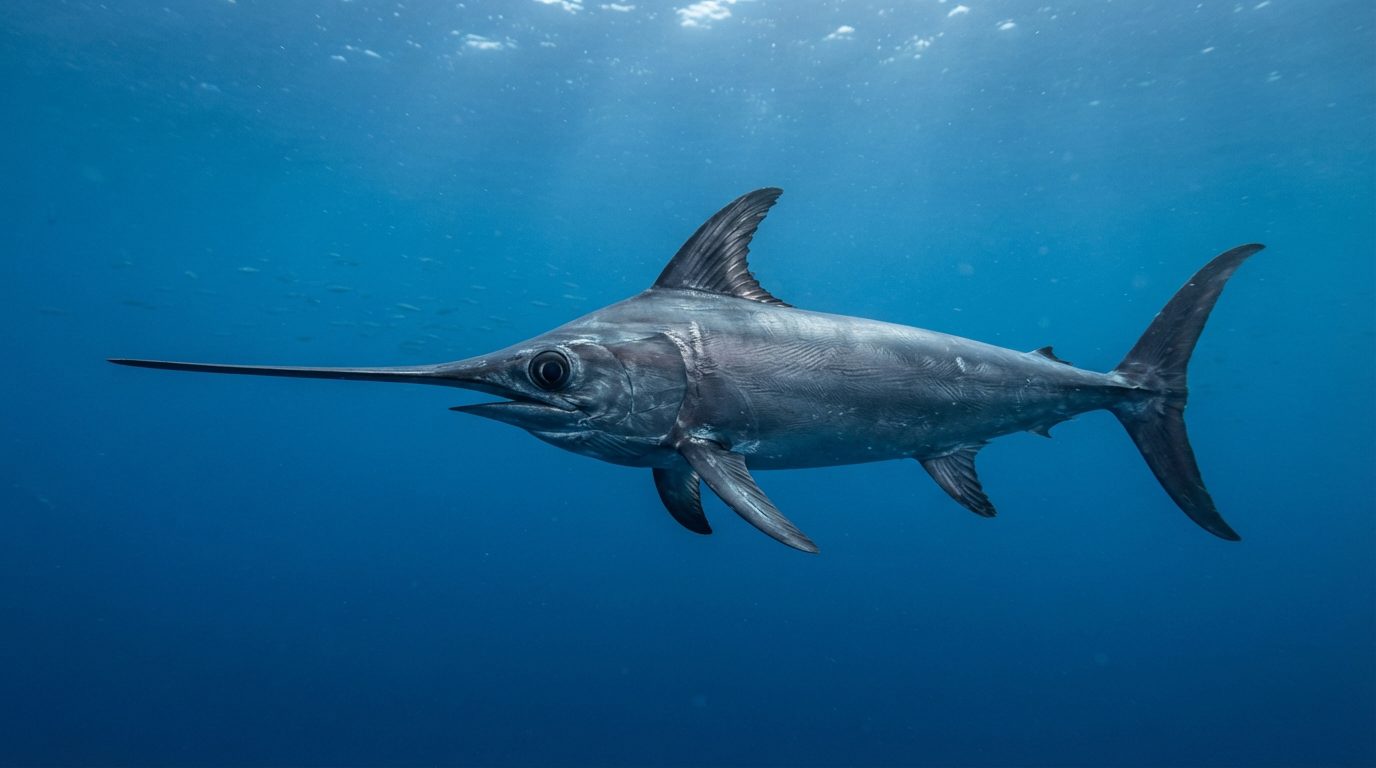
Acoustic beam width directly governs bottom resolution at deep-drop depths because a marine echosounder plots bottom depth based exclusively on the earliest acoustic return detected within its coverage footprint. An acoustic dead zone is the triangular volume of water near the seabed where the echo from an elevated feature arrives before the echo from a deeper target, rendering fish or structure inside that lower zone invisible on the sounder display. When targeting daytime swordfish (Xiphias gladius) between 1,200 and 2,000 feet, wider beams obscure steep, current-swept wall contours and replace defined breaks with misleading, upward-shifted bottom echoes.
The geographic area covered by an acoustic ping expands predictably according to basic trigonometry. Calculating this area requires the standard geometric formula:
\(\text{Cone Footprint Diameter} = 2 \times \text{Depth} \times \tan\left(\frac{\text{Beam Angle}}{2}\right)\)
According to engineering specifications published by Airmar Technology Corporation, beam angles are measured at the -3 dB acoustic power points. At a standard daytime swordfish depth of 1,800 feet (300 fathoms), an angler running a 25-degree High-Wide CHIRP transducer paints a seabed circle with a diameter of 798.1 feet. That acoustic circle covers 500,287 square feet of ocean floor in a single transmission. Conversely, a narrow 9-degree Low CHIRP beam produces a footprint diameter of 283.3 feet, reducing bottom seabed coverage to 63,037 square feet. For a complete tabular breakdown across mid-water and benthic columns, reference our CHIRP Cone Angle vs Depth (Pelagic Coverage Chart).
PING GEOMETRY ON A 20-FATHOM DROP
-----------------------------------
      [Transducer Ping]
              |
              v
       /---------------\
      /   9° Beam       \
     /    Footprint      \
    /     (283 ft)        \
   |                       |
===+==========\            |   <-- Shallow Edge
   |           \           |       Returns First
   | 20-Fathom  \          |
   | Drop-off    \         |
   | (120 ft)     \        |
   |               \       |
   |   DEAD ZONE    \======+   <-- True Deep Floor
   |   (Undetected)        |       Masked by Wide
   \-----------------------/       Return Envelope
This footprint geometry dictates how echosounders render bottom contours along abrupt drop-offs. The NOAA Office of Coast Survey Hydrographic Manual details how acoustic pulses detect the shallowest high-relief structure within the footprint first, regardless of whether that structure sits in the dead center or on the peripheral boundary of the beam. When a boat drifts over a 20-fathom (120-foot) vertical shelf at 1,800 feet with a 25-degree cone, the outer edge of the 798-foot footprint strikes the upper edge of the ledge long before the central beam strikes the bottom base. The fish finder interprets that first arrival as the true seabed, drawing an artificial, elevated plateau across the entire display.
A narrow 9-degree beam reduces that acoustic distortion by 64.5% compared to a 25-degree beam over identical terrain. Over that same 120-foot shelf, the 9-degree cone confines its returns to a compact 283-foot envelope, identifying the distinct shelf break far closer to the vessel’s true coordinate. When pairing your transducer selection with the hull considerations detailed in our 0° to 24° Transducer Deadrise Chart (Selection Guide), keeping beam angles tight directly prevents costly terminal tackle losses. If the sounder hides a sheer 120-foot wall under an artificially smoothed bottom trace, an angler dropping heavy weight calculated via our Daytime Swordfish Lead Sizing: 8lb to 18lb (Chart) will snag and anchor their rig into unmapped rock faces.
🧩 Puzzle: The Phantom Shelf
Two swordfish boats, Boat A and Boat B, drift directly beside each other over a steep canyon edge at 1,500 feet depth. Boat A runs an 8-degree beam and marks a flat bottom at 1,500 feet for two minutes before its screen shows a precipitous drop to 1,650 feet. Boat B runs a 24-degree beam over the exact same track, yet its sounder shows a flat bottom at 1,500 feet that continues for two minutes longer than Boat A’s display before registering any drop. Neither vessel changed speed or course. Why did Boat B record 400 extra feet of horizontal flat bottom that does not exist on the seabed?
Reveal the answer
Boat B’s wider 24-degree cone has a footprint diameter of 637 feet at 1,500 feet depth, compared to Boat A’s 210-foot footprint. As both boats drifted across the ledge, the trailing peripheral edge of Boat B’s wide cone remained pinned to the shallow 1,500-foot lip long after the vessel passed it. Because an echosounder plots the shallowest return within the cone first, Boat B’s unit rendered the shallow lip as the bottom until the trailing cone edge physically cleared the cliff edge.
Thinking move: Invert the assumption that sonar displays show what is directly beneath the keel; wide cones report the earliest range anywhere within the circle.
This acoustic lag explains why wide beams give anglers a false sense of safe drift margin over sharp breaks.
The severity of the acoustic dead zone also varies with bottom composition and hard-target reflectivity. Acoustic impedance research by marine geophysicist Dr. Alistair B. Hamilton demonstrates that basalt and carbonate hard-bottom structures return significantly stronger echoes at the beam periphery than soft silts return along the acoustic axis. Consequently, a rocky shelf on the outer fringe of a 25-degree cone easily overpowers weak sediment returns from directly below the boat.
Understanding the acoustic geometry that conceals benthic drop-offs sets the stage for evaluating the raw electrical output required to penetrate these depths. Below, we examine the decibel return levels and watt-hour draw differences between 1 kW and 3 kW Low CHIRP elements operating in deep water.
Low CHIRP Versus High-Wide Acoustic Performance Comparison
Low CHIRP transducers operating between 40 kHz and 60 kHz provide the sound penetration necessary to resolve the sea floor and individual swordfish marks past 1,500 feet, whereas High-Wide CHIRP delivers the fine vertical target separation needed to isolate pelagic bait clusters in the surface mixing zone.
Acoustic attenuation is the rate at which sound energy dissipates as it travels through seawater, driven by viscous absorption and chemical relaxation processes that weaken high frequencies far faster than low frequencies.
According to absorption equations published by F.H. Fisher and V.P. Simmons in the Journal of the Acoustical Society of America, 200 kHz sound waves experience an attenuation rate near 54 dB per kilometer in 10°C saltwater, compared to just 14 dB per kilometer for 50 kHz sound waves. Because acoustic energy must complete a round trip to the seabed and back, High-Wide frequencies shed their energy before reaching typical daytime swordfish depths of 1,600 to 2,000 feet.
| Metric / Variable | Low CHIRP (e.g., B175L, R509L) | High-Wide CHIRP (e.g., B175HW) |
|---|---|---|
| Nominal Frequency Band | 40 kHz – 60 kHz | 150 kHz – 250 kHz |
| Beamwidth (-3 dB points) | 16° to 25° (B175L) / 9° to 14° (R509L) | Constant 25° across entire band |
| Acoustic Bandwidth | 20 kHz | 100 kHz |
| Theoretical Range Resolution | ~37.5 mm (~1.5 inches) | ~7.5 mm (~0.3 inches) |
| Usable Detection Limit | 2,500 to 4,000+ feet (rig dependent) | 500 to 700 feet maximum |
| Coverage at 1,800 ft Depth | 506 ft to 800 ft diameter footprint | Unusable (energy lost to attenuation) |
| Primary Swordfish Role | Identifying deep bottom structure and fish | Tracking upper-column squid and thermoclines |
Dynamic vertical target separation depends directly on pulse bandwidth rather than transmitted frequency alone. The 100 kHz operational bandwidth of a High-Wide transducer gives sounder modules like the Garmin GSD 26 or Simrad S5100 an exceptional vertical range resolution of under 1 inch in the upper water column. You can evaluate how these cone footprints expand through the water column using our CHIRP Cone Angle vs Depth (Pelagic Coverage Chart).
Low CHIRP sweeps a narrower 20 kHz bandwidth, expanding real-world vertical target separation to roughly 4 to 8 inches after digital signal processing filters run. At 1,800 feet, however, high-resolution returns mean nothing if the acoustic pulse cannot return above the receiver’s thermal noise floor. Low-frequency sound waves bypass the scattering layer and biological thermocline boundaries, delivering the raw acoustic penetration needed to identify hard bottom ledges where daytime swordfish feed.
Power ratings fundamentally alter this acoustic dynamic when you fish high-current environments like the Gulf Stream, where drift speeds routinely measure 3.5 to 4.5 knots. A 1 kW flush-mount unit like the Airmar B175L houses a single ceramic element, which struggles to maintain bottom lock once current-induced aeration and boundary layer turbulence build across the hull. Selecting the proper tilt angle from the 0° to 24° Transducer Deadrise Chart (Selection Guide) prevents this hull aeration from blinding the crystal array.
Multi-element 2 kW and 3 kW commercial-grade housings such as the Airmar Technology Corporation R509L and CM599L use 25 separate low-frequency piezoceramic elements. This massive acoustic surface area produces a much narrower 9° beam at 60 kHz and dramatically increases acoustic sensitivity. The narrower beam concentrates acoustic energy onto a 285-foot diameter bottom footprint at 1,800 feet, rather than the sprawling 800-foot footprint cast by a wide-beam 1 kW transducer.
When drifting at 4 knots, maintaining vertical presentation requires matching your terminal tackle to hydrodynamics, as detailed in our guide on Daytime Swordfish Lead Sizing: 8lb to 18lb (Chart). A 3 kW Low CHIRP array punches through the surface cavitation and turbulent flow noise generated during these fast drifts, letting you track individual drop-weights and identify bottom transitions with zero signal dropout.
Correctly pairing transceiver power with your operating frequency solves the depth barrier, but aligning these acoustic cones to your hull’s true running attitude requires dialing in specific transceiver mounting offsets.
Transducer Housing Selection and Mounting Dynamics for High-Drift Sounding
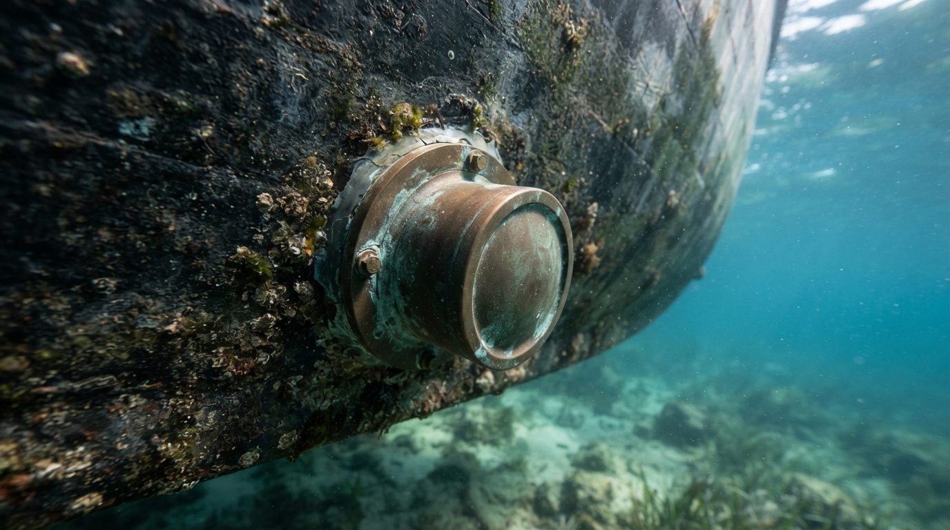
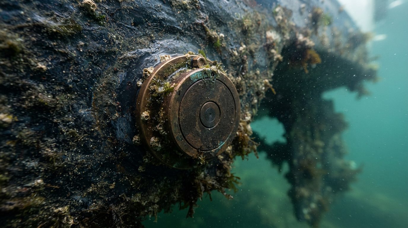
Securing clean acoustic returns from swordfish holding at depths of 1,200 to 2,000 feet requires isolating the ceramic elements from hull-induced aeration and boundary layer turbulence. While a flush tilted-element transducer like the Airmar B175L installs flat against the outer skin, external fairing blocks such as the B265LH and flush pocket mounts like the PM111LHW isolate signals into undisturbed water. Acoustic transmission losses escalate sharply if water passing across the transducer face contains entrained air bubbles or irregular pressure differentials.
A laminar boundary layer is a thin sheet of water directly adjacent to the hull that moves at a slower velocity than the surrounding displacement flow, remaining smooth until surface friction, hull strakes, or steps disrupt it into turbulent, bubble-bearing eddies.
According to fluid dynamics data published by the Naval Surface Warfare Center Carderock Division, turbulent boundary layer thickness increases linearly with running surface distance, often expanding past 25 millimeters along the aft running surface at speeds above 8 knots. When air bubbles within this aerated layer sweep across an active face, they scatter acoustic energy. This scattering causes catastrophic signal attenuation at frequencies above 130 kHz, where wavelengths measure less than 11.5 millimeters and interact directly with microbubble diameters.
HULL FLOW DYNAMICS
[ Hull Running Surface ]
          │
  Turbulent Boundary
  (Microbubbles & Noise)
          │
  ════════╧════════  <-- Acoustic Boundary
  Undisturbed Water
  (Clean Sounding Zone)
Flush thru-hull tilted elements like the 1 kW Airmar B175L remain popular on stepped center consoles because they create zero trailer bunk interference. However, their physical location directly inside the hull’s boundary layer degrades target detection whenever the vessel drifts beam-to-sea at 1.5 to 3.0 knots. Under heavy roll axis movement, the leeward side of the hull traps aeration along the keel, masking the low-frequency 40–60 kHz return that identifies swordfish on the bottom.
Anglers calculating hull angles can reference the 0° to 24° Transducer Deadrise Chart (Selection Guide) to confirm that the transducer’s internal ceramic matches the running surface within the mandatory 3-degree tolerance.
External fairing blocks like the Airmar High-Performance Fairing paired with a B265LH or B275LHW place the ceramic array 75 to 125 millimeters below the hull surface. This extension penetrates through aerated wash directly into clean, laminar water. The fairing’s elongated teardrop shape minimizes cavitation and directs water smoothly across the urethane face. The engineering trade-off is mechanical vulnerability: high-speed impacts with submerged debris can shear fairings, and they create drag that disrupts water flow to inboard running gear.
For large sportfishing convertibles and dedicated deep-drop hulls, in-keel tanks or pocket-mounted housings like the 2 kW PM111LHW and 3 kW CM599LHW provide the highest signal-to-noise ratio. Airmar Technology Corporation documentation indicates that the CM599LHW contains a 25-element low-frequency ceramic array measuring 361 by 112 millimeters. This massive surface area delivers an acoustic sensitivity gain roughly 6 to 9 decibels higher than single-element 1 kW units. A pocket mount installs flush with the external keel contour, eliminating hydro-drag while protecting the urethane face from impact.
Pro-Tip: When installing a pocket-mount tank (such as the CM599LHW cavity), fill the void around the urethane face entirely with marine-grade castable epoxy or propylene glycol to eliminate internal air pockets. A single 2-millimeter trapped air pocket against the inner ceramic face will reflect up to 99% of the sounder’s transmitted pulse power directly back into the element, causing severe thermal throttling.
Processing these low-frequency and high-wide signals requires interfacing the transducer with high-output sounder modules such as the Garmin GSD 26, Furuno DFF3-UHD, or Simrad S5100. These transceivers feature independent digital signal processors that govern power output from 250 W to 3 kW depending on the element’s operational impedance. The Furuno DFF3-UHD, for example, employs adaptive pulse-length synthesis, generating wide frequency sweeps between 25 and 45 kHz to punch through the water column while preventing acoustic ringing.
Acoustic ringing is an unwanted decay oscillation where a transducer’s ceramic element continues to vibrate physically after the transmit voltage pulse ceases, masking real target echoes that return during that time window.
To maximize target separation when picking out a swordfish holding 3 feet off a 1,750-foot mud bottom, transceiver pulse length must balance range resolution against power output. Calculating coverage footprints requires consulting the CHIRP Cone Angle vs Depth (Pelagic Coverage Chart) to ensure the selected beam width resolves individual fish without smearing bottom contours. At 1,800 feet, a standard 25-degree wide beam projects an acoustic footprint of 798 feet across the seabed, averaging out steep ledges and burying weak swordfish blips inside bottom returns.
Pro-Tip: When tracking your terminal rig on the drop, manually restrict the sounder module’s dynamic CHIRP sweep to 42–52 kHz on the low channel. This concentrates the module’s 2 kW or 3 kW output power across a narrow 10 kHz window, improving target return clarity on rigs mapped using the Daytime Swordfish Lead Sizing: 8lb to 18lb (Chart).
Signal processing algorithms on the Garmin GSD 26 and Simrad S5100 rely heavily on low electrical noise floors across the vessel’s DC bus. Running high-frequency CHIRP (150–250 kHz) alongside low-frequency sounding draws up to 8.5 amps under heavy pulse cycles. If the transducer cables share a chase with windlass or electric reel wiring, induced electromagnetic interference creates vertical noise bars across the display, degrading the system’s digital target separation.
Once your physical housing penetration and module interfaces provide a clean, noise-free return, you can examine the specific beam geometries and frequency sweeps that distinguish individual swordfish bills from schooling squid.
The Master Airmar Depth and Cone Angle Calculation Chart
A transducer beam footprint is the circular area of seabed illuminated by an acoustic pulse, calculated using the formula \(D = 2 \times Z \times \tan(\theta / 2)\), where \(D\) is the footprint diameter, \(Z\) is water depth, and \(\theta\) is the transducer beam angle at the -3 dB acoustic power threshold.
According to acoustic beam formulas published by Airmar Technology Corporation, narrow beam angles preserve acoustic energy density over long travel distances, whereas wide beam angles dilute signal returns across a broad footprint. Matching transducer selection to target depth requires balancing this spatial resolution against total seabed coverage. Anglers can cross-reference pelagic water-column coverage in our companion guide on CHIRP Cone Angle vs Depth (Pelagic Coverage Chart).
| Nominal Cone Angle | Beam Footprint at 1,000 ft | Beam Footprint at 1,400 ft | Beam Footprint at 1,800 ft | Beam Footprint at 2,200 ft | Primary Transducer Examples | Typical Frequency Band |
|---|---|---|---|---|---|---|
| 6° | 105 ft | 147 ft | 189 ft | 231 ft | R509LM, PM111LM | 40–60 kHz (Low CHIRP edge) |
| 9° | 157 ft | 220 ft | 283 ft | 346 ft | CM599LH, PM411LWM | ~38–50 kHz / Tuned Mid |
| 12° | 210 ft | 294 ft | 378 ft | 462 ft | B175L, TM265LH | 40–50 kHz (Low CHIRP) |
| 16° | 281 ft | 393 ft | 506 ft | 618 ft | B275LHW, B175M | 85–135 kHz (Mid CHIRP) |
| 20° | 353 ft | 494 ft | 635 ft | 776 ft | B175H | 130–210 kHz (High CHIRP) |
| 25° (Constant HW) | 443 ft | 621 ft | 798 ft | 975 ft | B175HW, PM275LHW | 150–250 kHz (High-Wide) |
At 1,800 feet, a 25° High-Wide transducer paints a 798-foot circle on the bottom. The acoustic power spreads over an area 17.8 times larger than that of a 6° narrow beam, dropping return signal strength by roughly 12 dB. If hull deadrise offsets the beam axis by more than 3°, that wide footprint degrades bottom tracking further; verify proper tilt matches using the 0° to 24° Transducer Deadrise Chart (Selection Guide).
Tracking a stick lead and terminal rig through high-current layers down to 1,800 feet requires precise sonar tuning. Pair this sounder protocol with proper downrigger or sash weights documented in our Daytime Swordfish Lead Sizing: 8lb to 18lb (Chart).
4-Step Sounder Calibration Protocol for Deep-Drop Tracking
-
Establish Manual Gain Threshold
Disengage auto-gain on your multi-function display. Increase manual gain until bottom noise manifests as a continuous dusting of static 50 to 100 feet above the seabed contour, then back the gain down by 3% to 5% until the water column clears while maintaining a solid 4-pixel bottom line. -
Sync Scroll Speed to Drift Velocity
Set display ping rate to maximum (or 100%), then calibrate chart scroll speed directly against GPS drift speed over ground (SOG). For drifts under 1.5 knots, run scroll speed at 1/1 (equal to ping rate); for drifts between 1.5 and 3.5 knots, increase scroll speed to 2X or "Fast" to stretch returns horizontally, preventing a 10-pound sash weight from compressing into bottom clutter. -
Clamp Time Variable Gain (TVG) to Low
Time Variable Gain (TVG) is an acoustic signal processing curve that amplifies weaker, distant returns while suppressing strong, near-surface echoes to produce visually uniform target sizes throughout the water column. For bottom-tracking swordfish weights, set TVG to "Low" (or an empirical 2 to 3 out of 10) in your Simrad or Garmin sounder menus; high TVG values suppress weak deep returns, erasing a 5-inch sash weight echo within 30 feet of hard bottom. -
Sweep Discrete Frequencies to Bypass Stratified Thermoclines
When running a broadband transceiver such as the Furuno FCV-295 or NavNet TZT3, switch off auto-CHIRP and initiate 2 kHz stepped manual sweeps between 38 kHz and 48 kHz. Deep salinity layers and density boundaries bend acoustic waves through refraction; shifting transmit frequency by as little as 4 kHz bypasses destructive interference, resolving your sash weight as an unbroken falling diagonal trace.
Managing line lay and avoiding false drop signals during these calibration descents also depends on spool tension, as detailed in the Deep-Drop Braid Tension Matrix (With Spool Worksheet).
Transducer choice depends entirely on hull layout and your primary target spread.
For a dedicated tournament swordfish hull fishing bottom contours from 1,200 to 2,200 feet, the standard installation is an Airmar R509LHW or dual-tank R111LM paired with a 2 kW or 3 kW transceiver like the Simrad S5100. The Low channel (28–60 kHz) operates at a razor-sharp 5° to 9° cone angle, focusing sounder wattage directly under the keel to resolve individual fish within 15 feet of bottom structure.
Versatile mixed-spread center consoles target both pelagic billfish in the upper 300 feet and daytime swordfish on the seabed. For these vessels, install a dual-transducer pocket: an Airmar B175L (40–60 kHz, 32° to 21° beam) paired with a B175HW (150–250 kHz, constant 25° beam). The B175HW paints a continuous 443-foot window across the upper water column at 1,000 feet to intercept surface-feeding tuna and marlin, while the B175L punches down with low-frequency energy to confirm deep-drop bottom contact.
Input your boat’s draft, transducer model, and deadrise offset into your MFD today, set your sounder to discrete low-band CHIRP, and lock in manual gain before dropping your first weight.
Sources & Further Reading
Airmar transducer selection for deep-drop swordfishing depends on balancing acoustic attenuation with ocean-floor footprint size, pairing low frequencies between 42 kHz and 65 kHz for depths beyond 1,500 feet with high-wide frequencies for scanning bait in the upper water column.
Acoustic attenuation is the loss of energy as sound waves propagate through seawater, driven by viscous absorption and thermal conduction that convert acoustic pressure into heat.
As John Simmonds and David N. MacLennan document in Fisheries Acoustics: Theory and Practice (2005), absorption losses compound exponentially as sonar frequency climbs. A 200 kHz signal loses signal strength far too rapidly to return clean target echoes from a swordfish hull at 1,800 feet. Conversely, low-band CHIRP pulses preserve signal-to-noise ratios across extreme depths, punch through thermal stratifications, and register swimbladder returns against muddy bottom structure.
Acoustic footprint geometry dictates target resolution. According to technical documentation published by Airmar Technology Corporation, a wide 25° beam spreads acoustic energy over a bottom circle wider than 790 feet at a depth of 1,800 feet. That wide cone dilutes acoustic return energy and smears bottom contour lines into indistinguishable clutter. Francis G. Carey and Bruce H. Robison demonstrated in their study in Fishery Bulletin (1981) that daytime swordfish orient tightly to deep bathymetric ledges between 1,400 feet and 2,100 feet. A narrow low-frequency cone angle between 4° and 11° concentrates transmitter wattage into a tight footprint, isolating benthic drop-offs and individual targets.
- Airmar Technology Corporation, Chirp Transducer Technical Reference Guide (2021) – outlines ceramic array design, transducer impedance thresholds, and beam coverage formulas for marine hydroacoustics.
- John Simmonds and David N. MacLennan, Fisheries Acoustics: Theory and Practice (Blackwell Science, 2005) – establishes quantitative models for sound propagation, absorption loss, and marine organism backscattering cross-sections.
- Robert J. Urick, Principles of Underwater Sound (McGraw-Hill, 1983) – provides foundational sonar equations covering transmission loss, boundary reflections, and oceanic noise dynamics.
- Francis G. Carey and Bruce H. Robison, "Daily patterns in the activities of swordfish, Xiphias gladius, observed by acoustic telemetry" (Fishery Bulletin, 1981) – tracks diurnal vertical migration depths and daytime benthic feeding behavior along slope edges.
- National Oceanic and Atmospheric Administration, Atlantic Pelagic Longline Observer Program Data Summary (NOAA Fisheries, 2020) – details daytime swordfish capture depths, sea surface temperature interactions, and thermocline boundaries.